
Oscilloscope Clock II - Further Development Notes
Introduction
My scope clock 2 uses a DG7/32 CRT - this is my reference design and I have modified it to suit other CRTs. Only CRTs that I have tested the scope clock with (and I present photographs and movies below) will be shown. But the design should work with many similary tubes.
| Parameter | DG7/32 | DP7/5 | 2AP1 | E4103/B/4 | DH3/91 |
| Final Anode volts |
500 | 800 | 500 — 1000 | 1000 | 500 |
| Focus Anode volts |
0 — 120 | 200 — 300 | 125 — 250 | ? | auto |
| Grid (note 1) volts |
-50 — -100 | 0 — -50 | -30 — -60 | -25 | -16 — -54 |
| X sensitivity mm/V |
0.35 — 0.43 | 0.16 | 0.13 — 0.26 | 0.10 | 0.19 |
| Y sensitivity mm/V |
0.22 — 0.28 | 0.26 | 0.11 — 0.22 | 0.09 | 0.22 |
Note 1: for extinction of an undeflected, focused spot

Left to right, DG7/32, DP7/5, 2AP1, E4103/B/4 and DH3/91
Quick Links
- main scope clock 2 description
- introduction
- 2AP1 CRT
- DP7/5 CRT
- E4103/B/4 CRT
- DH3/91 CRT
- Modified PSU
2AP1 CRT
Gallery
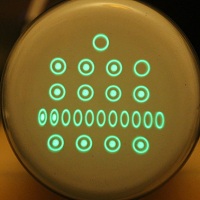
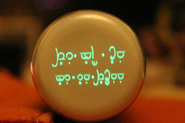
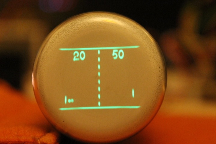
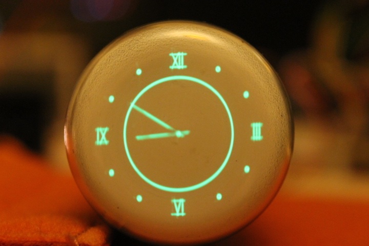
Hover the mouse over these screenshots for more information:


")


Power supply changes
This tubes permit operation at a slightly higher anode voltage than the DG7/32 reference design but close enough to make any changes to cathode voltage unnecessary. The required grid voltage is lower (as a negative voltage, i.e closer to the cathode voltage). The required changes represent a simplification of the reference design as the grid supply voltage doubler is no longer required.
DP7/5 CRT
Gallery
The DP7/5 has a short blue phosphor and a long persistence greenish yellow phosphor. These photographs were taken with the correct exposure to show the blue colour (one only) but then over exposed to show the long persistence afterglow. The afterglow is subtle as shown with the room lights on when it disappears. But the blue colour itself is very appealing.
Hover the mouse over these screenshots for more information:


 with historical documentry")

Power supply changes
This tubes permit operation at a slightly higher anode voltage than the DG7/32 reference design but close enough to make any changes to cathode voltage unnecessary. The required grid voltage is lower (as a negative voltage, i.e closer to the cathode voltage). The required changes represent a simplification of the reference design as the grid supply voltage doubler is no longer required.
E4103/B/4 CRT
This is an old WW2 British CRT made by GEC. The tube diameter is about 38mm and the usable screen is some 25mm in diameter. There is little information available on it but I did get it working from this information.
I have two of these old CRTs and unfortunately they both have some points where the phosphor is burned.
Gallery
Power supply changes
Perhaps this does illustrate how flexible the clock design is as with only a little adaptation I had the CRT working in about an hour. The two changes I had to make were to reduce the grid blanking voltage to -21V by changing the grid supply transformer to a single 15V RMS winding and to supply the tube with a 4V 1A heater supply (I did this using PWM control of a MOSFET from the 6.3V AC supply, more on this technique later). The CRT is suppose to require an anode voltage of 1000V but I tested it using the 800V available.
DH3/91 CRT
Gallery


Power supply changes
This tubes permit operation at a slightly higher anode voltage than the DG7/32 reference design but close enough to make any changes to cathode voltage unnecessary. The required grid voltage is lower (as a negative voltage, i.e closer to the cathode voltage). The required changes represent a simplification of the reference design as the grid supply voltage doubler is no longer required.
I have no intention of making a scope clock 2 using a DH3/91. The purpose here was to test the CRT and present the photographs and movies above. For this reason a separate power supply PCB design with the parts omitted has not been developed. It is only necessary to replace C14 with a link and omit D12. Also, the tube deflection is asymetric with deflection plate D1' connected to the final acceleration anode connection (pin 2: g2, g4, D1'). This means that one connection to the collector of the final deflection amplifer transistor is omitted. On review, I think some further tweaks to the PSU might be worthwhile. But I have demonstarted the CRT in operation.
Power supply schematics and boards
These tubes permit operation at a slightly higher anode voltage than the DG7/32 reference design. The required grid voltage is lower (as a negative voltage, i.e closer to the cathode voltage). The required changes represent a simplification of the reference design as the cathode supply voltage reduction and the grid supply voltage doubler are no longer required. Other changes are as noted.
These board are reduced version of the DG7/32 design; I have not renumbered them so the parts are not sequentially numbered but have an exact correspondence with the previous design.
The Eagle files can be downloaded here.


I found myself missing the right sort of base for the 2AP1 CRT so I quickly made one:


Power Supply Board Parts List
| Part | Description | Farnell Code | Rapid Code | Dimensions |
| C1 | 100u 16V | 1236662 | 2.5mm lead spacing 7mm diameter |
|
| C2 | 2200u 16V | 9692215 | This part is 25V 7.5mm lead spacing 16mm diameter |
|
| C3 | 10u 16V | 9451480 | 2.5mm lead spacing 5mm diameter |
|
| C4, C5 & C6 | 100n | 9750983 | 5mm lead spacing 2.5mm x 7.5mm package |
|
| C7, C8 & C11 | 220u 400V | 8813582 | 10mm lead spacing 25mm diameter |
|
| C10 | 1u 630V | 1200810 | 27.5mm lead spacing 13.4mm x 31.6mm package |
|
| C13 | 1u 250V | 9693980 | 2.5mm lead spacing 7.5mm diameter |
|
| C15 | 100u 250V | 1673472 | 7.5mm lead spacing 16mm diameter |
|
| R1 | 390 5% 0.25W | 62-0360 | ||
| R2 | 1k trim pot | 9354298 | Bourns 3362P series; brightness control; see note 2 | |
| R3 | 330 5% 0.25W | 62-0358 | ||
| R4 | 10k 5% 0.25W | 62-0394 | ||
| R5, R7, R12 & R16 | 470k 5% 0.25W | 62-0434 | ||
| R6 | 1M8 5% 0.25W | 62-0448 | ||
| R10 | 500k pot | 9354395 | Bourns 3362P series; focus control; see note 3 | |
| R17 | DP7/5: 1M 5% 0.25W 2AP1: 680k 5% 0.25W |
62-0442 62-0438 |
||
| D1 & D2 | 1N4001 | 9564993 | ||
| D3 | UF1G | 1625267 | ||
| D4 | 1N4148 | 9565124 | ||
| D5, D7 & D9 | 1N4007 | 9565051 | ||
| D11 | 1N4004 | 1843708 | ||
| Q1 | BC327 | 9558489 | ||
| Q2 | ZTX558 | 9526676 | ||
| IC1 | 78L05 | 1014073 | The pcb layout shows TO220 package; the L device is adequate | |
| IC2 | 6N137 | 9994866 | ||
| X1 | Connection to CRT heater | see note 1 | ||
| X2 | Blanking input from digital card | see note 1 | ||
| X3 | External brightness control (if used) | see notes 1 & 2 | ||
| X4 | Connection to CRT cathode, control grid and focus anode | see note 1 | ||
| X5 | Connection to analogue card | see note 1 | ||
| X6 | External focus control (if used) | see notes 1 & 3 | ||
| X7 | Connection to transformers | wire links or else see note 1 | ||
| X8 | Connection to digital card | see note 1 | ||
| X9 | Unused connection | see note 1 | ||
| socket for IC2 | 8 pin DIL socket | 22-0107 | ||
Notes
- 0.1" pin header strip with everyother pin removed; wires soldered and covered with heatshrink tube
- The brightness control (R2) can be either a 1k trimpot on the PCB or an external mounted 1k pot connected using X3
- The focus control (R10) can be either a 500k trimpot on the PCB or an external mounted 500k (or 470k) pot connected using X6
| Part | Description | Farnell Code | Rapid Code | Dimensions |
| Mill-Max Receptacle | 11 required | Mouser (UK link) part 575-03900 | ||
| X1 | CRT connection to Analogue and PSU cards | 0.1" header pin strip with every other pin removed | ||
Transformer Board Parts List
The board is optional. See schematic for 115V or 230V operation.
| Part | Description | Farnell Code | Rapid Code | Dimensions |
| Transformer A | 230V RMS 10mA, 13.5V RMS 200mA, 6.3V RMS 1A | Transformer TRA800 from Ask Jan First |
||
| Transformer B | 2 x 22V RMS 1.6VA | 9531360 | note 2 | |
| F1 | 0.5A | 26-0167 | 20 x 5mm holder | |
| X1 | Transformer B wires | see note 1 | ||
| X2 | Mains supply | screw connector, 5.08mm spacing, 3 way | ||
| X3 | Outputs to PSU PCB | see note 1 | ||
| X4 | Transformer A wires | see note 1 | ||
Notes
- 0.1" pin header strip with everyother pin removed; wires soldered and covered with heatshrink tube
- The test with the E4103/B/4 CRT used a 1 x 15V transformer