Introduction
This is a 24 hour clock using nixie display tubes. The catch is there are no semiconductors used - all the the active components are neon filled or vacuum state devices. Professionally made printed circuit boards have been used and the clock is now running on test awaiting the construction of the case.
A limited number of partial kits, including the PCBs are available, details below.

This design uses about 100 vacuum valves and neon filled tubes and bulbs. Over 300 resistors, over 200 capacitors, a custom wound mains trasformer and so it is not a small project. But there is no microcontoller or its software in sight. It uses filtered and conditioned mains frequency as a timebase for counting. With a few component changes, the clock will operate with either 50 or 60Hz mains and operate on 230V or 115V mains.
The clock uses mains and high voltages, over 400V DC is present in the clock. For safety, the clock must be earthed correctly and any exposed metal parts earth bonded. Under no circumstances should the power supply be modified for direct mains operation and the transformer omitted. This is not a project for a beginner in electronics perhaps.
My first attempt at building an all valve/tube clock using trigger tubes was not entirely successful as the counter rings tended to stall in complete darkness due to the trigger tube (XC18) used. The design presented on this page uses the Z700U trigger tube which has a keep-alive electrode ensuring that a ready supply of photons are always hitting the cathode so the trigger tubes ignites when you want them to, even in complete darkness.
Quick Links
- introduction
- references
- schematics, layouts & parts
- power supply
- 1Hz timebase
- seconds & minutes display
- hours display
- inter-board wiring
- clock longevity
- physical build
- I trigger tubes circuits
- II display design by JB Dance
- III consolidated parts list
- IV partial kit
- V licence & copyright
- first trigger tube clock
References
This clock is based on material published in books or based on designs by others found on the internet. The key referenced materials are:
- A bulletin from Philips "Subminiature Trigger Tubes Z70U Z70W"
- A section in "Electronic Counting Circuits" by JB Dance and reproduced below in Annex II
- By Morris Odell "Vacuum Tube 1Hz Relay Timebase"
- Mullard Technical Handbook "Cold Cathode Tubes" 1963
- "Cold Cathode Tube Circuit Design" DM Neale D.Van Nostrand Inc 1965, chapters 3, 4 & 5 in particular
See also Annex III which contains a longer description of how trigger (or relay) tubes work.
Quick LinksSchematic, Layouts and Parts
Introduction
This section presents the four types of board that make up the clock:
- Power supply
- Timebase
- Seconds and minutes count and display
- Hours count and display
How these boards are interconnected is also described
Parts lists based on UK (where I live) or some European specialist suppliers are presented. In some cases Ebay will be found the best place to find the components cheaply.
Annex III contains a consolidated parts list for the whole clock and Annex IV a partial kit of parts that I will have available (while stocks last).
Power Supply
Introduction

The power supply must deliver:
- about +430V DC for the hours/minutes/seconds count and display boards
- about +150V DC and stabilised +280V DC for the timebase board, reset and other general functions
- 6.3V RMS AC for valves with heaters
- about 450V RMS AC for the colon indicators
- about 200V peak halfwave pulses for the timebase board
- about -30V DC bias supply
In trying to achieve this range of voltages at the current demand it proved difficult to find a standard off-the-shelf transformer. The relatively expensive (but well engineered and safe) option of a custom wound transformer was taken and a unit bought from Airlink Transformers in the UK.
The transformer specification is:
- primary: 230V AC RMS 50Hz
- secondary 1: 400 - 0 - 400V AC RMS @ 50mA
- secondary 2: 6.3V AC RMS @ 1.5A

This transformer cost about £100 including tax and postage and took about 7 days from ordering to arrival. I am very pleased with it, as I have been with other transformers I have bought from Airlink. It has part number TT4902-CPr. Obviously, if you live in 115V/60Hz land then you need to specify a different primary.
If you use another transformer then a few resistor values in the PSU may need adjustment. Specifically, referring to the schematic below:
- The rectifier anode resistors (R5 & R6) should be adjusted to give about 450V DC at the cathode of the rectifier. The operating envelope of the EZ90 rectifer must not be abused and the resistance of the half secondary winding plus the resistor value used must exceed 525Ω
- The filter/dropper resistor (R4) should be adjusted to give 430V DC at the filter exit (output connector X8)
- The heater series resistor (R31) should adjusted to give 6.3V AC RMS on the heaters including replacement with a wire link if the voltage from the tranformer is exact or low
- The potential divider resistor (R15) should be adjusted to the highest value possible that gives sufficient halfwave pulse peak voltage (output connector X16) to reliably trigger the timebase pulseshaper
It should not be necessary to adjust the other dropper resistors (R8 & R11).
Schematic
The PSU board also contains the circuits to drive the nixie separator colons, generate the correct reset voltages and a once per second relay click to generate a pleasing (IMHO) tick-tock sound and optionally flash the separator colons.

V1 is the main rectifier double diode valve and after smoothing provides +430V for the count and nixie display boards. After a further dropper resistor, V2 and V8 provide stabilised +300V and after a further dropper resistor, +280V is provided for the timebase board, reset and colon flashing counters.
One transformer secondary is use to feed the colons with AC power. This means that both electrodes in the colons glow. The colons can be omitted, can be permanently illuminated or made to flash at 0.5Hz (i.e. on of 1 second, off for 1 second) using the contacts on relay K1.
The other transformer secondary is used to feed a potential divider. The first tap is rectified by one half of an EB91 double diode but is unsmoothed. This diode provides halfwave pulses at 50 or 60Hz to the timebase board. A lower tap on the potential divider is rectified by the other half of the EB91 diode. This rectifier is smoothed and produces about -30V DC as a bias voltage to the grid of V7 holding the tube fully cut-off normally.
V4 and V5 form a binary counter that changes state once per second. The cathode of V5 drives the grid of V7 so that V7 conducts and relay K1 closes. V3 is a reset tube in parallel with V4 so that the relay K1 is de-energised during a reset. This circuitry accomplishes two things: a distictive tick-tock sound as the relay is energised and de-energised and the relay contacts can be used to flash the colon neons. V3, V4, V5, V7, K1 and their associated resistors and capacitors are optional and are not required for the clock to function. An optional switch, S3, in th anode circuit of V7 can be used to silence the relay (and this will also prevent the colons from flashing).
The arrangement of the colon neons is not fixed. The schematic shows four neon bulbs, NE1 to NE4 but more or less can be used. It shows them is a simple series arrangement but they could be arranged in pairs so they flash alternately. Optional switch, S1, can be arranged to force the neons on, or off or to take their supply from the contacts of K1. This versitility and the possibility of not using the specified colon neon type means that the series resistor (R3) value may need to be recalculated.
Finally, switch S2 forms a clock reset switch. Closing its contacts causes the reset line voltage to rise from about 140V to 280V. This voltage is applied to the trigger electrodes of the reset tubes throughtout the clock and will cause them to ignite. The timebase divider rings will be halted and initialised, the time counter and display rings will all be set to "00" and the tick-tock relay will be de-energised while in reset. It might be wise to prevent the accidental operation of the reset switch!
PCB Layout
The single sided PCB measures about 90 x 160 mm. The board emits heat from the vacuum valve heaters, stabiliser tubes and dropper resistors and should be appropriately ventillated.

Parts List
| Part | Description | Farnell Code | Rapid Code | Dimensions |
| C1 - C4, C7 | 22u 350V | 1673478 | 5 mm lead spacing 13 mm diameter |
|
| C5 - C6 | 100p 200V | 1216414 | 5 mm lead spacing 2.4 x 4.4 mm package see note 2 |
|
| C8 - C9 | 6n8 400V | 1166029 | 5 mm lead spacing 3 mm x 7.5 mm package see note 2 |
|
| C10 | 10u 250V | 9693262 | 5 mm lead spacing 10 mm diameter |
|
| R1, R2, R7, R8, R13, R14 |
470k | 9339566 | 62-0434 | 0.25W 5% |
| R3 | 470k | 9339566 | 62-0434 | 0.25W 5% see notes 1 & 2 |
| R4 | 500R | 1W 5% Ebay |
||
| R5, R6 | 1k | 4W 5% Ebay |
||
| R9 | 6k8 | 4W 5% Ebay |
||
| R10 | 18k | 9339256 | 62-0400 | 0.25W 5% |
| R11 | 1k8 | 2W 5% Ebay |
||
| R12, R25 | 47k | 9339558 | 62-0410 | 0.25W 5% |
| R15, R26, R30 | 220k | 9339329 | 62-0426 | 0.25W 5% |
| R16 | 1M | 9339086 | 62-0442 | 0.25W 5% |
| R17- R19 | 1M2 | 1186236 | 62-0444 | 0.25W 5% |
| R20 | 120k | 9339140 | 62-0420 | 0.25W 5% |
| R21 - R24 | 10M | 1186248 | 62-0466 | 0.25W 5% |
| R27, R28 | 56k | 9339612 | 62-0412 | 0.25W 5% |
| R29 | 4M7 | 1186244 | 62-62-0458 | 0.25W 5% |
| R31 | 0R62 | 2W 5% |
||
| V1 | EZ90 | Ebay 6X4, CV493, U78 |
||
| V2, V8 | 150C2 | Ebay OA2, 150C4, M8223 CV1832, STR150/30 AG5211, CV2903 |
||
| V3 - V5 | Z700U | Ebay Z70U |
||
| V6 | EB91 | Ebay 6AL5, 6D2, CV140, DD6, M8212, D152, EAA91 |
||
| V7 | EC90 | Ebay CV133, CV852, 6C4, L77, V741 |
||
| NE1 - NE4 | Neon bulbs | 42-0300 | or Ebay See note 2 |
|
| K1 | 110VDC coil DPDT |
51-0516 | Finder 40.52.9.110 | |
| T1 | Custom transformer | Airlink Transformers Part TT4902-CPr |
||
| V1, V2, V6-V8 | B7G valve bases | plastic 17mm PCD ask-jan-first FAS025 |
||
| X1 - X25 | Spade connector 2.8 x 5 mm |
male: 4215527 female: 3625400 |
see note 3 | |
Notes:
- Omit if colon neons are not fitted
- Series neon resistor (R3) valve depends on colon neon arrangement
- The connectors are on a 5.08mm spacing so many other connectors can be freely used
- See Annex III for a consolidated parts list and Annex IV for a partial kit
- The descriptions are for those parts I used. Other parts could well be suitable e.g. different capacitor voltage ratings
Mains wiring
For safety, the clock must be earthed correctly and any exposed metal parts earth bonded. Under no circumstances should the power supply be modified for direct mains operation and the transformer omitted.
For safe operation of the clock there mains wiring should include a double throw switch, an appropriately rated fuse and a gland to anchor the cable. Such a scheme is shown here and also includes a line filter to hopefully clean up noise on the mains supply.

| Part | Description | Farnell Code | Rapid Code | Dimensions |
| G1 | Cable gland | 10066120 | 04-1922 | |
| S1 | Double throw switch | 2128066 | 75-0185 | Mains Rated |
| F1 | Fuse Holder | 1081795 | 26-1577 | 1A fuse |
| L1 | Line Filter | 2353469 | 50-3968 | |
Notes:
- These are exemplar parts
- The Rapid parts are in the partial kit see Annex IV
1Hz Timebase
Introduction
The timebase board takes rectified and unsmoothed positive halfwave pulses at mains frequency from the power supply board. The schematic is based on Figures 32 and Figure 33 in the Phillips reference. Few changes have been made, mainly to the power supply and reset arrangements.

Schematic

V2 and V3 form a flip-flop circuit to deliver pulses into the counter rings. The relatively long time constant of the cathode circuits prevent the flip-flop being triggered more than once during a half-wave pulse. Pulses across the common cathode resistor are of the correct amplitude and shape to feed into the first counter ring. V1 is used to start or reset the flip-flop.
V5 to V10 form a divide by 6 counting ring for operation with a mains frequency of 60Hz. For operation with a mains frequency of 50Hz one of the tubes (and associated resistors and capacitors) is omitted to form a divide by 5 counting ring. Any of the tubes can be omitted except V5 and V10 as these have other circuits attached. V4 has common cathode and anode connections with V5 and is used to start or reset the ring by pulsing its trigger electrode (this technique is used in many places in this clock design). V11 is the "carry" detector and is used to drive the next ring with a 10Hz signal by passing one pulse every six (60Hz mains) or five (50Hz mains) pulses received.
V13 to V22 use the same basic circuit as the first ring except it has 10 stages to form a divide by 10 counting ring. V12 is the ring start/reset tube and V23 is the carry tube which passes 1Hz pulses to the seconds counting/display board and to the PSU board to operate the tick-tock relay flipflop.
PCB Layout
The single sided PCB measures about 75 x 160 mm.

Parts List
| Part | Description | Farnell Code | Rapid Code | Dimensions |
| C1, C10, C11 | 100n 250V | 1215481 | 10 mm lead spacing 5.4 x 13.3 mm package |
|
| C2 - C8, C18 - C28 |
100p 200V | 1216414 | 5 mm lead spacing 2.4 x 4.4 mm package see note 2 |
|
| C9 | 1n 200V | 2383396 | 5 mm lead spacing 3 mm x 7.5 mm package |
|
| C12-C17, C30-C39 | 6n8 400V | 1166029 | 5 mm lead spacing 3 mm x 7.5 mm package see note 2 |
|
| C29 | 10n 250V | 9750991 | 5 mm lead spacing 3 mm x 7.5 mm package |
|
| R1, R2 | 1M8 | 1186238 | 62-0448 | 0.25W 5% |
| R3-R13, R37-R48 | 1M2 | 1186236 | 62-0444 | 0.25W 5% see notes 1 & 2 |
| R14-R24, R49-R60 | 10M | 1186248 | 62-0466 | 0.25W 5% see notes 1 & 2 |
| R25-R32 R61-R70 |
56k | 9339612 | 62-0412 | 0.25W 5% see note 2 |
| R33, R71 | 680k | 9339680 | 62-0438 | 0.25W 5% |
| R34, R72 | 100k | 9339078 | 62-0418 | 0.25W 5% |
| R35, R36, R73 | 18k | 9339256 | 62-0400 | 0.25W 5% |
| V1-V23 | Z700U | from Ebay see note 2 |
||
| X1-X6 | Spade connector 2.8 x 5 mm |
male: 4215527 female: 3625400 |
see note 3 | |
Notes:
- The descriptions are for those parts I used. Other parts could well be suitable e.g. different capacitor voltage ratings
- 50Hz: omit V9 stage (C6, C16, R11, R22, R31) and bridge R12 across missing stage:
 60Hz: fit V9 stage
 - The connectors are on a 5.08mm spacing so many other connectors can be freely used
- See Annex III for a consolidated parts list and Annex IV for a partial kit
Minutes & Seconds
Introduction
The minutes and seconds board both count and display 00 to 59 and are identical. The seconds board takes the 1Hz signal from the timebase board and send one pulse per minute to the minutes count and display board. In turn the minutes board sends one pulse per hour to the hours count and display board.

Nixie Selection
The original design used the Z520M nixie. My build was to use the physically similar Z560M nixie. During initial testing I found that the rings would not correctly count or reset. Measurement showed the common anode voltage to be higher than 280V at 285V. I increased the common anode resistor value from 150k to 180k and the problem was corrected. Any change to the nixie used might require the common anode resistor and/or the nixie anode resistor value to be changed for correct operation. If the common anode voltage is too high the rings will not reset and if too low they will not count.
Schematic
V1 and V2 are the two display nixies. They are shown on the schematic to illustrate how they are connected to the trigger tube counters. They are not mounted on the PCB.
V12 to V21 are the ten units count and display ring stages. V11 is in parallel with V12 and is used to reset the ring to 0. V22 is the carry detector and sends a pulse to the tens ring when the units ring count and display is changed from 9 to 0.
The tens count and display ring is the same as the units ring except it has only 6 stages. V4 to V9 are the stages, V3 the reset to 0 tube and V10 the carry detector tube which sends a pulse to the next board when the display changes from 5 to 0.

PCB Layout
The single sided PCB measures about 90 x 160 mm.

Parts List
| Part | Description | Farnell Code | Rapid Code | Dimensions |
| C1-C6, C14-C19, C22-C31, C43-C52 |
10n 250V | 9750991 | 5 mm lead spacing 3 mm x 7.5 mm package |
|
| C7 - C13, C32 - C42 |
100p 200V | 1216414 | 5 mm lead spacing 2.4 x 4.4 mm package |
|
| C20, C53 | 330p 200V | 2383395 | 5 mm lead spacing 2.6 mm x 4 mm package |
|
| C21, C54 | 2n2 1kV | 9527230 | 5 mm lead spacing 6 mm package |
|
| R1, R35 | 180k | 9339264 | 62-0424 | 0.25W 5% see note 1 |
| R2, R3 | 27k | 9339370 | 62-0404 | 0.25W 5% see note 2 |
| R4-R9, R36-R45 | 68k | 9339671 | 62-0414 | 0.25W 5% |
| R10, R46 | 470k | 9339566 | 62-0434 | 0.25W 5% |
| R11, R47 | 1M2 | 1186236 | 62-0444 | 0.25W 5% |
| R12-R18, R48-R58 | 1M | 9339086 | 62-0442 | 0.25W 5% |
| R19, R59 | 1k | 9339051 | 62-0370 | 0.25W 5% |
| R20-R27, R60-R71 | 10M | 1186248 | 62-0466 | 0.25W 5% |
| R28-R33, R72-R81 | 33k | 9339434 | 62-0406 | 0.25W 5% |
| R34, R82 | 220k | 9339329 | 62-0426 | 0.25W 5% |
| V1, V2 | Z560M | from Ebay or ask-jan-first etc see note 2 |
||
| V1, V2 | B13B socket | from Ebay or ask-jan-first etc |
||
| V3-V22 | Z700U | from Ebay | ||
| X1-X22 | Spade connector 2.8 x 5 mm |
male: 4215527 female: 3625400 |
see note 3 | |
Notes:
- R1 & R35 are dependant on the type of nixies V1 & V2; see main text
- R2 & R3 are not mounted on the PCB but close to the nixie
- The connectors are on a 5.08mm spacing so many other connectors can be freely used
- See Annex III for a consolidated parts list and Annex IV for a partial kit
- The descriptions are for those parts I used. Other parts could well be suitable e.g. different capacitor voltage ratings
Hours
Introduction
This board takes one pulse per hour from the minutes count and display board. It counts and displays hours in the range 00 to 23. The board is different to the previous board in that the count from 23 to 24 must be detected and the count reset to 00. Whereas the seconds and minutes just use simple ring counters.

Schematic

Displaying 01-12 hours
An alternative to counting and displaying 00 to 23 is to count and display 01 to 12 hours. This could be accomplished with a design that has a units ring of 10 (0 to 9) and a tens counter of 2 (0 and 1). The design must detect the carry from 12 to 13 and reset the board to 01. With a fairly complex multipole switch it should be possible to have a clock that can be switched bewteen displaying 00 to 23 and 01 to 12. Lastly, a flipflop and two neon bulbs could be added as AM/PM indictors. The flipflop would change state when a count of 12 is detected.
I have not tested or implemented these ideas!
PCB Layout
The single sided PCB measures about 90 x 160 mm.

Parts List
| Part | Description | Farnell Code | Rapid Code | Dimensions |
| C1-C3, C9-C11, C15-C24, C36-C45 |
10n 250V | 9750991 | 5 mm lead spacing 3 mm x 7.5 mm package |
|
| C4 - C8, C25 - C35 |
100p 200V | 1216414 | 5 mm lead spacing 2.4 x 4.4 mm package |
|
| C12, C46 | 330p 200V | 2383395 | 5 mm lead spacing 2.6 mm x 4 mm package |
|
| C13, C47 | 2n2 1kV | 9527230 | 5 mm lead spacing 6 mm package |
|
| C14 | 1u 350V electrolytic |
1907167 | 2 mm lead spacing 5mm diameter |
|
| R1, R31 | 180k | 9339264 | 62-0424 | 0.25W 5% see note 1 |
| R2 | 120k | 9339140 | 62-0420 | 0.25W 5% |
| R3, R4 | 27k | 9339370 | 62-0404 | 0.25W 5% see note 2 |
| R5-R7, R33-R42 | 68k | 9339671 | 62-0414 | 0.25W 5% |
| R8, R29, R30, R43 | 470k | 9339566 | 62-0434 | 0.25W 5% |
| R9 | 100k | 9339078 | 62-0418 | 0.25W 5% |
| R10 | 12k | 9339132 | 62-0396 | 0.25W 5% |
| R11, R16, R32 | 1M2 | 1186236 | 62-0444 | 0.25W 5% |
| R12-R14 R17, R18, R44-R54 |
1M | 9339086 | 62-0442 | 0.25W 5% |
| R15, R55 | 1k | 9339051 | 62-0370 | 0.25W 5% |
| R19-R24, R56-R67 | 10M | 1186248 | 62-0466 | 0.25W 5% |
| R25-R27, R68-R77 | 33k | 9339434 | 62-0406 | 0.25W 5% |
| R28, R78 | 220k | 9339329 | 62-0426 | 0.25W 5% |
| K1 | 110VDC coil DPDT |
51-0516 | Finder 40.52.9.110 | |
| V1, V2 | Z560M | from Ebay or ask-jan-first etc see note 2 |
||
| V1, V2 | B13B socket | from Ebay or ask-jan-first etc |
||
| V3-V20 | Z700U | from Ebay | ||
| X1-X18 | Spade connector 2.8 x 5 mm |
male: 4215527 female: 3625400 |
see note 3 | |
Notes:
- R1 & R31 are dependant on the type of nixies V1 & V2; see main text
- R3 & R4 are not mounted on the PCB but close to the nixie
- The connectors are on a 5.08mm spacing so many other connectors can be freely used
- See Annex III for a consolidated parts list and Annex IV for a partial kit
- The descriptions are for those parts I used. Other parts could well be suitable e.g. different capacitor voltage ratings
Overall Inter-Board Wiring
Finally, here are some notes on how the 5 boards are wired togther. Rather than try to present a single, complex schematic, the inter-board wiring is broken down into a series of drawings:
Inter-board Power
To transfer +430V, +280V, +150V and common ground to the other boards as required.

Inter-board Reset Signal
The reset switch should be a momentary action toggle switch or push button. It should be protected from accidental operation or the current clock time will be lost.

Interboard Timing Pulses
This wiring transfers timing pulse signals between the boards and three switches allow the clock time to be set. The switches are shown in their normal operating position. To set the time on the clock a proceedure such as this would be used:
- The run/set switch is operated. This disconnects the 1 Hz pulses from the seconds board input and so the clock ceases counting
- The reset switch (see above) can be momentarily pressed to put the clock in a known state
- The fast minutes switch can be operated to send 1Hz pulses into the minutes board so the minutes board will count quickly and the switch can be thrown back when the minutes displayed are correct
- The fast hours is operated in the same way to quickly advance the hours displayed
- Finally, the run/set switch is thrown back to restart the clock counting from the set hours and minutes displayed.

Colon Neon Wiring
Some individuality can be employed in wiring the colon neons. (The colon neons act as separators between the hours and minutes nixies, and the minutes and seconds nixies. As in HH:MM:SS, where the colon ":" represents two neon bulbs.) Here four examples are shown.

Parts List
| Function | Action Required | Notes |
| Tick Tock | SPST off - on |
Connects to X10 & X14 on PSU Board |
| Clock Reset | Momentary SPST off - (on) |
Connects to X2 & X4 on PSU Board See reset drawing above |
| Run/Set | DPST off - on |
See timing drawing above |
| Fast Minutes | Momentary DPST off - (on) |
See timing drawing above |
| Fast Hours | Momentary DPST off - (on) |
See timing drawing above |
| Colon Neon Example 4 | DPST 3 position on - off - on |
See colon drawing above |
Clock Longevity
There are four types of component in the clock which might be consider to have a limited life.
Trigger tube life
The Phillips Z70U booklet says "The life expectancy in counting circuits is longer than 30,000 hours" or about 3½ years. If this is the actual time ignited then the following must be considered:
- On the PSU board the tick-tock flipflop trigger tubes are each ignited 50% of the time
- On the timebase card the pulse shaper trigger tubes are each ignited 50% of the time
- On the hours count/display card the "0" and "1" hour trigger tubes are each ignited about 42% of the time
- All the remaing trigger tubes are ignited for <20% of the time
Little can be done to extend the life of the trigger tubes so it is recommended that a few spare tubes are purchased to guard against future unavailability.
Nixie tube life
In modern microcontroller based clocks steps can be taken to extend tube life. This clock is far more primative and little can be done by the clock itself to extend tube life. The following might be considered:
- Ensure the tubes operate at the correct current and adjust the anode resistor value as necessary
- Occassionally rotate tube positions that are fully used (all the units nixie tubes) with those where not all of the cathode are used (all the tens nixies). But bear in mind the stress on the tube of removing and re-inserting the tube in the sockets, so this advice is two edged
Relay life
The relays used have a mechanical operating life exceeding 20e6 cycles. The hour relay cycles only once per day suggesting a life exceeding 55,000 years - good enough. The tick-tock relay cycles every 2 seconds which gives a life exceeding only 1¼ years. There are three ways forward:
- Do nothing - other references suggest actual mechanical operating life of a relay should exceed 1e9 cycles or over 60 years in this duty
- Turn of the tick-tock when not required to extend the life
- Expect the relay to fail; it should be possible to use 8 small MillMax receptacles to enable the relay to be plugged into the board for easy replacement. Part from ask-jan-first FAS901 perhaps.
Personally, I'm going to solder the relay in place and go with the "do nothing" option to see what actual relay life I achieve.
Vacuum valves and stabiliser tubes
These components will wear with time and must be expected to fail eventually. The valves and stabiliser tubes used have long lives, many equivalents and a readily available from specialist suppliers and on Ebay. No action should be necessary but purchase a spare set if you wish.
Quick LinksPhysical Build
Schematics and Layouts
You should look in the "/Nixie Projects/All Tube Trigger Clock 2" folder.
Under Test
All of the boards were home-made and tested before the set of commercial boards were ordered. The home-made boards and now the pro-made have run for a couple of months under test without fault. The clock runs 24/7 including complete darkness without a glitch. Here's the current board set roughly wired together for testing:

The case design is work in progress...
Quick LinksAnnex I Trigger Tube Circuits
About
Although the cold cathode diode is sometimes used as a counter device, for the majority of applications it suffers from one or more of the following shortcomings:
- the breakdown potential is not a controlled characteristic
- striking may be subject to statistical delays
- input and output share the same pair of terminals.
Several kinds of three- and four-electrode tubes are available which eliminate some or all of these shortcomings. In construction, they vary considerably, but in principle they represent a simple logical development from the neon diode. The main anode-cathode gap of a such a tube has all the characteristics of a gas-filled diode. If the applied voltage exceeds a given value, Vig, ignition or breakdown occurs. As long as the current is restricted to the range corresponding to a normal glow discharge, the maintaining voltage, Vm, is substantially constant. As in a simple diode, breakdown cannot occur unless free electrons or ions are present in the gap. Photoemission or ionisation by natural radiation or a radioactive isotope in the envelope produce ion currents so small that the breakdown voltage is not usually dependent on their magnitude. As a rule, only direct sunlight will produce sufficient photoemission to reduce the value of Vig. In a cold cathode triode, however, the additional electrode provides an alternative means whereby a substantial ionisation of the main gap may be produced. When a sufficiently high potential is applied between this trigger electrode and cathode, a discharge occurs between these two electrodes. Provided the trigger current exceeds a critical value known as the transfer current, sufficient ionisation of the main gap is produced to promote a discharge from anode to cathode. This occurs even though the anode voltage is less than Vig, but it must, of course, be greater than the maintaining voltage, Vm, to which the anode voltage falls once ignition occurs.
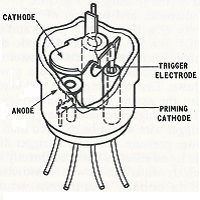
Figure: Z700U Construction

The trigger gap also has the characteristics of a cold cathode diode, and accordingly, it, too, cannot strike without a source of primary electrons. In a trigger tube it is usually required that triggering shall occur as quickly as possible once the appropriate potentials have been applied. Accordingly, natural radiation cannot be relied upon to produce primary ionisation, as considerable delays would frequently arise between application of the trigger potential and ionisation of the gas filling by a cosmic ray. Even the inclusion of a radioactive material, such as uranium oxide or tritium, leaves a significant statistical delay. Accordingly, two alternative types of trigger tube have been evolved:
- Those in which the cathode is coated with a material of low work function, e.g. an oxide of barium or potassium. Such a coating will emit electrons under the influence of light entering the glass envelope. These electrons then provide the primary ionisation neces-sary for triggering to occur.
- Tubes using pure metal cathodes, usually molybdenum. The pure metal has a higher work function than an oxide coating, and as a result its photoemission is confined to ultraviolet wavelengths in the band absorbed by the glass of the tube envelope. Consequently, photoemission due to external radiation cannot be used to produce primary ionisation. An alternative source is provided in a small continuous priming discharge across an auxiliary electrode gap. An external series resistor is used to restrict this discharge to some tens of μA, and this low current is not itself enough to cause triggering of other interelectrode discharges. Some ions or photons do, however, enter the trigger-cathode gap, and so provide primary ionisation allowing triggering to occur as soon as the trigger-cathode breakdown voltage, Vt, is reached.
One sees that the trigger tube when called a "relay" tube is most aptly named. Application of the requisite trigger potential allows the photoemission or priming discharge to initiate breakdown of the trigger-cathode gap. Discharge of the trigger circuit in turn supplies the greater degree of primary ionisation needed to cause ignition of the main gap at an anode voltage below Vig. Ionisation is thus "relayed" from primary source to main gap once the trigger potential reaches Vt. This justification of the name relay tube is only incidental: its true origin lies in the considerable power gain between input and an "off-on" output.
Ignition Characteristics
Figure: Characteristics of a typical trigger tube, indicating electrodes between which initial breakdown occurs

This figure represents the ignition characteristic of a typical trigger tube. Provided the voltage applied to the trigger electrode and anode are represented by a point lying within this characteristic, ignition does not occur. If one or both of these voltages is increased until the working point reaches or passes outside the characteristic, breakdown occurs. Operation is usually confined to the first quadrant, and breakdown is then initially between trigger and cathode or anode and cathode, depending on whether it is the trigger voltage or the anode voltage which is increased to move the working point beyond the characteristic. It will be seen, however, that if the trigger and/or anode voltage can become sufficiently negative the initial breakdown will occur in either direction between any pair of electrodes. With many circuits, particularly those operating with A.C. supplies, such triggering can occur unintentionally and must be guarded against. If current flows into the nominal anode or trigger some of the nickel may be sputtered on to the normal cathode, hereby contaminating the cathode surface. In tubes having pure metal cathodes this produces a permanent change in the otherwise very stable triggering characteristic of the tube.
Once breakdown occurs, the anode voltage falls to the anode-main-Inkling voltage, Vn. The trigger then acts as a probe in the anode-cathode discharge and tries to assume the trigger maintaining potential, Vn. This it will do provided the trigger current is limited to a few μA by a sufficiently large resistance in the trigger circuit. It should be noted that reverse trigger current will flow if the trigger supply potential is allowed to fall below Vn while the anode gap is conducting.
Triggering does not occur instantaneously. Between application of the trigger pulse and the establishment of anode current a delay time T arises which is the sum of:
- the statistical delay in the trigger-cathode breakdown
- the formative delay time elapsing between the start of the trigger breakdown avalanche and the formation of the positive space charge
- the time required for the trigger discharge to produce breakdown of the main gap; and
- the time required for the main gap current to rise to a given level.
It has been noted already that the first of these delays becomes long and unpredictable if a tube relying on photo-emission is operated in the dark. Even with the inclusion of a small amount of uranium oxide, delays may be as long as 100 msec, and accordingly, high-speed trigger tubes use pure metal electrodes and an auxiliary priming discharge. Provided the priming discharge is sufficiently large (usually between 10 and 250 μA), the statistical variation in practically disappears.
Trigger Tube Circuits
Having provided some general blurb on how trigger tubes operate, it is time to look at some practical but simple circuits used in the clock. Circuits to ignite and extinguish a trigger tube, and then how these are combined to form more complex circuits. In particular, reset circuits and ring/chain counters will be described as they are used throughout the clock.
Igniting Trigger Tubes
There are a variety of methods that can be used to trigger the tube ignition. The technique used in clock are current triggering and pulse-plus-bias triggering. The other technqiues that have been developed will be ignored here.

(a) Current Triggering
It is a pre-requisite that Vs > Vt. There is then a relationship between the tube parameters, Vs and the value of Rt. In practice Vs can be much larger than Vt to ensure triggering.
(b) Pulse-Plus-Bias Triggering
A positive bias, Vs, is applied which is sufficiently less than Vt so that no triggering occurs. A positive going pulse Vp is applied through capacitor Cp, which again, in itself is insufficient to ignite the tube. However, when the bias is applied and then the pulse applied triggering can be made to occur. This can be compared to a logic 'AND' gate. However, pulse-plus-bias triggering is better described as bias-before-pulse triggering. It is essentially a logical process of 'A' before 'B' rather than a true 'AND' gate.
Extinguishing Trigger Tubes
The methods by which a trigger tube may be extinguished are similar to those available for a diode. In trigger tubes, however, the anode-cathode and trigger-cathode discharges must both be extinguished.
(a) Series-switched Extinguishing

The simplest way of extinguishing a cold cathode tube comprises opening a switch in the +H.T. supply.
(b) Common-anode-load Extinguishing

Although other arrangememts are possible, a common arrangement comprises shunting the cathode resistors, Rk1 and Rk2, by suitably large capacitance, Ck1 and Ck2. While V1 is conducting, Ck1 charges to an equilibrium value. When V2 is triggered the cathode of V1 is held positive by Ck1, while that of V2 is initially at ground because Ck2 has yet to charge up. If the circuit time-constants are correctly chosen, V1 cathode will remain above V2 cathode long enough for V1 to deionise.
(c) Common-cathode-load Extinguishing
This arrangement is identical to the common-anode-load methode except the common resistor is in the cathode circuit.
(d) Self-Quenching

A trigger tube may be made self-quenching by using an appropriate series resistance, Ra, and shunt capacitance, Cq. When the tube strikes, the voltage across the gap falls to its maintaining voltage. The capacitor discharges rapidly, producing heavy ionisation of the tube. Consequently, although no further ionisation takes place once the gap voltage has fallen to the maintaining voltage, the removal of ions from the gap constitutes a continued flow of current. If this exceeds the current flowing in the series resistor the capacitor will be discharged below the normal maintaining voltage. As the ion current decreases, the capacitor will begin to recharge. Provided that it takes longer than the deionisation time to reach the gap voltage for which is the deionosation time is quoted, the discharge will not immediately restrike.
A resistor, Rq must be connected in the capacitor discharge path to limit the peak discharge current to a value which will not damage the tube.
A cathode series resistor, Ro, is also used to develop a positive output pulse at low impedance. Thus a self-quenching discharge may be used to generate sharp, low-impedance pulses that can be used to apply pulses simultaneously to the triggers of a number of tubes, as in pulse-plus-bias triggering.
Chain and Ring Counters
This figure is representative of a class of counting circuit based on pulse-plus-bias logic. A chain of n similar stages is often formed into a closed ring by connecting Vn to V1 in the same way as V1 is connected to V2 and V2 to V3. Common-anode-load extinguishing ensures that only one tube conducts at a time.
Suppose V1 is conducting. The voltage drop across Vk1 raises the trigger of V2 to a little below triggering potential. The triggers of all other tubes are at earth potential. When a positive-going pulse Vp is applied simultaeously to all triggers it follows that V2 will fire but providing that Vp < tube trigger voltage, none of the other tubes will fire. Firing of V2 quenches V1 and applies a priming bias to V3. Thus at the next pulse V3 will strike and V2 extinguish.
Positive-going outputs may be taken from the cathodes of individual tubes in the ring or chain.
Reset Circuits
In practical applications it is often needed to set the state of counters, flip-flops etc when the equipment is first switched on, or to reset to this staring state when the equipment is running. The chain or ring counter is an example where reseting the count to '0' is often required.

This example of a reset circuit uses a additional trigger tube, V0, in parallel with the first counter tube, V1. When a pulse, Vreset, is applied to the trigger of V0 causing it to ignite, the counter tubes are extinguished and the reset tube is left burning. When the next counter pulse, Vp, is applied, V0 will be extinguished and V2 will ignite.
Application of these circuits
This ring/chain counters and reset circuits are used throughout the clock:
- Pulses at mains frequency are fed into a ring of n=5 for 50Hz mains (or n=6 for 60Hz mains). One output pulse is generated by V5 (or V6) for every 5 (or 6) unit pulses. These pulses will be at a frequency of 10Hz.
- Pulses at 10Hz are fed into a ring of 10 tubes so the output pulses will be at a frequency of 1Hz.
- A ring of 10 tubes and then of 6 tubes will count 60 seconds and produce one output pulse every minute. The output pulse is taken from the cathode of V6 in the second ring so that it is produced at the same time that the seconds count changes from "59" to "00".
- The minutes rings are identical to the seconds rings and one output pulse is produced per hour.
- A ring of 10 and then a chain of 3 (i.e. with no feedback loop) are used to count hours and, for a 24 hour clock, both rings must be reset to 00 when the rings try to step to "24". Some extra logic is neede to detect this.
Each ring or chain counter has a reset circuit.
Quick LinksAnnex II J.B. Dance says
In Chapter 3 of Electronic Counting Circuits by J.B. Dance (Iliffe Books Ltd 1967) it says:
3. Single Cathode Gas Filled Counting Tubes and Their Circuits
…
3.4.7 Digital Readout from Trigger Tube Circuits
Although trigger tubes are inherently self indicating, it is usually much more convenient to use one digital indicator tube per decade to display the state of the count than to observe the ten trigger tubes in each decade themselves. The indicator tubes display one digit each as a neon glow. They have one common anode and the current passes from this to any one of ten cathodes. Each of the cathodes has the shape of one digit. One cathode is covered by a red glow when the tube is operating. Further details of digital indicator tubes are given in Chapter 10.
The digit which is being displayed at any specified time is determined by which cathode is passing current at that time. The selection of this cathode is carried out by the counting circuit itself. Each trigger tube in the decade circuit is connected to one of the ten indicator tube cathodes. When a particular trigger tube is conducting, the circuit must be arranged so that the corresponding cathode of the indicator tube is at a lower potential than that of the other indicator tube cathodes. The tube then indicates the appropriate number corresponding to the number of the trigger tube in the ring.

Fig. 3.12 A Z700U decade counter with Z520M readout
A typical circuit is shown in Fig. 3.12; it uses Z700U trigger tubes and the Z520M numerical indicator tube. The Z700U trigger tube V10 in the input circuit of Fig. 3.12 converts any incoming pulses into pulses of a suitable amplitude and duration for the operation of the other ten Z700U tubes which perform the counting operation. Pulses from the cathode of V10 are fed along the pulse line to the trigger electrodes of the counting tubes via 100 pF capacitors. The V10 circuit has a capacitor between the anode of the tube and earth and is, therefore, self extinguishing.
The counting tube anodes are fed through the common anode load resistor marked R1 (150k). In addition a smaller resistor (68k) is included in the anode circuit of each individual tube. These resistors are necessary for the operation of the indicator tube, but are by-passed by capacitors so that they do not affect the counting operation itself. The cathodes of the Z520M tube which are not shown in Fig. 3.12 as being connected to any particular trigger tube anode are actually connected to the trigger tubes in between V1 and V9; these trigger tubes have been omitted for simplicity.
If a trigger tube is conducting, its anode will be at a lower potential than the anodes of the other counting tubes owing to the flow of anode current through the 68k anode resistor. There will therefore be a greater voltage between the Z520M anode and the cathode of the Z520M which is connected to the conducting trigger tube than between the Z520M anode and any other cathode. Thus the cathode which is connected to the conducting trigger tube becomes the preferred cathode for the discharge and the Z520M indicates the corresponding number.
The common anode resistor, R1, enables a tube to be extinguished when the discharge is transferred to a succeeding tube by the same mechanism as that discussed previously in connection with the circuits of Figs. 3.5 and 3.7.
If a suitable negative pulse is applied to the cathode of VO via the 0.01u capacitor, the discharge will be transferred to VO and thus the decade will have been reset.
The maximum counting speed will be similar to that of the circuit of Fig. 3.8. If desired, Z700W tubes could be used for reversible counting with the Z520M as indicator. A circuit similar to that shown in Fig. 3.12 should be used with the additional trigger electrodes of the Z700W tubes arranged so that the circuit is symmetrical in both the forward and reverse directions.
…
Annex III Consolidated Parts Lists
This Annex lists the parts required for a complete clock build.
| Quantity | Description | Farnell Code | Rapid Code | |
| 72 | 100p 200V | 1216414 | 5 mm lead spacing 2.4 x 4.4 mm package |
|
| 6 | 330p 200V | 2383395 | 5 mm lead spacing 2.6 mm x 4 mm package |
|
| 1 | 1n 200V | 2383396 | 5 mm lead spacing 3 mm x 7.5 mm package |
|
| 6 | 2n2 1kV | 9527230 | 5 mm lead spacing 6 mm package |
|
| 18 | 6n8 400V | 1166029 | 5 mm lead spacing 3 mm x 7.5 mm package |
|
| 91 | 10n 250V | 9750991 | 5 mm lead spacing 3 mm x 7.5 mm package |
|
| 3 | 100n 250V | 1215481 | 10 mm lead spacing 5.4 x 13.3 mm package |
|
| 1 | 1u 350V electrolytic |
1907167 | 2 mm lead spacing 5mm diameter |
|
| 1 | 10u 250V | 9693262 | 5 mm lead spacing 10 mm diameter |
|
| 5 | 22u 350V | 1673478 | 5 mm lead spacing 13 mm diameter |
|
| 6 | 1k | 9339051 | 62-0370 | 0.25W 5% |
| 1 | 12k | 9339132 | 62-0396 | 0.25W 5% |
| 4 | 18k | 9339256 | 62-0400 | 0.25W 5% |
| 6 | 27k | 9339370 | 62-0404 | 0.25W 5% |
| 45 | 33k | 9339434 | 62-0406 | 0.25W 5% |
| 2 | 47k | 9339558 | 62-0410 | 0.25W 5% |
| 20 | 56k | 9339612 | 62-0412 | 0.25W 5% |
| 45 | 68k | 9339671 | 62-0414 | 0.25W 5% |
| 3 | 100k | 9339078 | 62-0418 | 0.25W 5% |
| 1 | 120k | 9339140 | 62-0420 | 0.25W 5% |
| 6 | 180k | 9339264 | 62-0424 | 0.25W 5% |
| 9 | 220k | 9339329 | 62-0426 | 0.25W 5% |
| 15 | 470k | 9339566 | 62-0434 | 0.25W 5% |
| 2 | 680k | 9339680 | 62-0438 | 0.25W 5% |
| 53 | 1M | 9339086 | 62-0442 | 0.25W 5% |
| 33 | 1M2 | 1186236 | 62-0444 | 0.25W 5% |
| 2 | 1M8 | 1186238 | 62-0448 | 0.25W 5% |
| 1 | 4M7 | 1186244 | 62-62-0458 | 0.25W 5% |
| 85 | 10M | 1186248 | 62-0466 | 0.25W 5% |
| 1 | 0R62 | 2W 5% |
||
| 1 | 500R | 2W 5% Ebay |
||
| 2 | 1k | 4W 5% Ebay |
||
| 1 | 1k8 | 2W 5% Ebay |
||
| 1 | 6k8 | 4W 5% Ebay |
||
| 1 | EZ90 | Ebay 6X4, CV493, U78 |
||
| 1 | EB91 | Ebay 6AL5, 6D2, CV140, DD6, M8212, D152, EAA91 |
||
| 1 | EC90 | Ebay CV133, CV852, 6C4, L77, V741 |
||
| 2 | 150C2 | Ebay OA2, 150C4, M8223 CV1832, STR150/30 AG5211, CV2903 |
||
| 5 | B7G valve bases | plastic 17mm PCD ask-jan-first FAS025 |
||
| 85 | Z700U | Langrex or Ebay equivalent Z70U |
||
| 4 | Neon bulbs | 42-0300 | or Ebay | |
| 6 | Z560M | from Ebay or ask-jan-first etc |
||
| 6 | B13B socket | from Ebay or ask-jan-first etc |
||
| T1 | Custom transformer | Airlink Transformers Part TT4902-CPr |
||
| 2 | 110VDC coil DPDT |
51-0516 | Finder 40.52.9.110 | |
| 93 | Spade connector 2.8 x 5 mm |
male: 4215527 female: 3625400 |
||
| 1 | Cable gland | 10066120 | 04-1922 | |
| 1 | Double throw switch | 2128066 | 75-0185 | Mains Rated |
| 1 | Fuse Holder | 1081795 | 26-1577 | 1A fuse |
| 1 | Line Filter | 2353469 | 50-3968 | |
| Tick Tock | SPST off - on |
|||
| Clock Reset | Momentary SPST off - (on) |
|||
| Run/Set | DPST off - on |
|||
| Fast Minutes | Momentary DPST off - (on) |
|||
| Fast Hours | Momentary DPST off - (on) |
|||
| Colon Neon | DPST 3 position on - off - on |
Example 4 | ||
Notes:
- The descriptions are for those parts I used. Other parts could well be suitable e.g. different capacitor voltage ratings
- The selection of the switches depends on the physical build and so no Farnell or Rapid parts number are given
Annex IV Partial Kit Availability
At this time I hope to be able to sell a limited number of partial kit of parts. For a cost of £125 included are:
Sold Out Sorry!
- Set of PCBs (5 items)
- Complete resistor kit (346 items)
- Complete capacitor kit (204 items)
- Board-wire spade connectors (male & female, 200 items)
-
Miscellaneous parts (11 items)
- mains lead gland
- mains switch
- mains fuse holder
- mains fuse
- mains filter
- relays (2)
- neon bulbs (4)

Not included are paypal charges, postage and, if not in the EU, any import duties dependant on where you live. The partial kit is complete for both 50Hz and 60Hz operation.
The nixies and their bases, the vacuum valves, stabiliser tubes and their bases and the trigger tubes are all readily available on Ebay or suppliers such as ask-jan-first. I see little reason to buy them for reselling as I will not be able to offer any discount on their prices; the parts would be more expensive as I would have to pay (and pass on to you) the postage.
The custom transformer (or any other transformer for that matter) is a single expensive and heavy item which it is not sensible for me to buy on your behalf; again the postage hurts.
I cannot offer items which are dependant on your individual build and case design. This is really the control switches and hook up wire in practice.
Contact me via the email address on the "Contact us" page if you are interested.
Quick LinksAnnex V Licence & Copyright
Trigger Tube Clock II is an open design based on the original designs given in the reference section above. The design and hardware files are released under the GNU General Public License v3.
Trigger Tube Clock II is Copyright © 2014 Grahame Marsh.
This design is free; you can redistribute it and/or modify it under the terms of the GNU General Public License as published by the Free Software Foundation; either version 3 of the License, or any later version.
Trigger Tube Clock II is distributed in the hope that it will be useful, but WITHOUT ANY WARRANTY; without even the implied warranty of MERCHANTABILITY or FITNESS FOR A PARTICULAR PURPOSE. See the GNU General Public License for more details.
You can read a copy of the GNU General Public License at http://www.gnu.org/licenses/gpl-3.0.html; if not, write to the Free Software Foundation, Inc., 51 Franklin Street, Fifth Floor, Boston, MA 02110-1301 USA , or see http://www.gnu.org.
Quick Links