Introduction

This clock came about after some experiments using simple two electrode neon bulbs in ring counters. The initial experiments I hoped would produce a clock where the neon bulbs would both count and display the time; no nixie was intended to be used. I found the large (10 or 12) step counters somewhat cranky and subject to misfiring, or having problems with more than one neon fired in a ring. I then came across a book by J.B. Dance that described ring counters using three electrode trigger tubes. This seemed a better approach if the old trigger tubes count be found. I thought of using thyratrons (like the EN91) but the idea of the heater current alone rather put me off, but even so I thought a short thyratron ring could be an interesting experiment.
I was then searching (Google) for trigger tube data sheets, trigger tubes in general and, much to my amazement, found a supply of the XC18 trigger tubes in England. I found no sign of the XC24 four electrode trigger tube and so could not get a reset to zero on power-up to work in the way that Dance describes.
The supplier also had the XC18 datasheet.
Progress…

At this point, armed with a handful of trigger tubes (a handful = just over one hundred) a nixie clock based on trigger tube ring counters become a real project. I built a 4 stage ring counter on my breadboard to convince myself that the ring did trigger and advance in the way it should. Next was a simple stabilised PSU and half wave rectified 50Hz power supply for the nixie anode supply.
I then built a divide by 10 ring followed by a divide by 5 ring to take 50Hz down to 1Hz. (People in 60Hz land just need an additional stage to divide by 6 rather than 5). The nixie anode supply was clamped with a small neon bulb and sufficient signal passed into the 10 ring to cause it to trigger. After a few solder bridges were removed the two rings fired successfully, the only change made was to increase the common anode resistor values from the Dance value to account for the 216v stabilised PSU output.
Next came a divide by 10 followed by a divide by 6 "seconds" count and display board. Each ring counter element has a nixie driver to connect to a cathode of a nixie. So this card has 32 trigger tubes in total. The "minutes" card is obviously identical.
The "hours" card proved more tricky. At the start I wanted a 12/24 switchable display with the option of suppressing a leading zero display:
00..23 or 0..23 or 01..12 or 1..12

At some stage I gave up on this and left the design as it stands now with only a 12 hour suppressed leading zero display i.e. 1..12. This happens to be the format that SHMBO prefers, and perhaps a necessary element for transferring the finished clock from the workshop into the house… Setting the time is accomplished by switching the 1 Hz pulse into the minute board or the hour board. It can take a couple on minutes to get the time set but it then runs happily until power is lost for what ever reason.
The circuit diagrams (downloads) were produced using Eagle. You will see a huge amount of repetition as the same single element of the counter stage is replicated. This was the first project I have undertaken with Eagle (not for profit version) so please forgive my perhaps clumsy use of the package. But I found the routed PCB layouts fantastic. The boards are size to fit on 100mm x 160mm standard PCB size, or a cut down version of it. PCBs are all made at home: Eagle, LJ4 onto film, UV exposure box, ferric chloride bath and then drill using 0.8mm and 1mm drill bits as required by the components.
Construction
The main chassis is 3mm aluminium sheet annealed and folded. The holes for the nixies were made by punches. The nixies bases are on a sub-assembly which stands behind the front panel. The nixies poke through in a "bug-eyed" fashion. Statically lit colons are made using small neon bulbs mounted on small PCBs with their current limiting resistors. Ventilation holes are drilled both under the PSU board and in the back panel to allow some draft (I am concerned about dust intake however dirtying the inside of the clock) through the case.
Main inlet socket, fuse and switch are all mounted on the back panel.
The clock will be finished with a transparent cover (2mm polycarbonate sheet hopefully) fixed on angle aluminium (holes are drilled in the chassis for this but are not yet fixed in place.
The chassis is painted with "Hammerite" silver/grey hammer finish - but this doesn't show up too well in the photos.
Schematics


PCB
You should look in the "/Nixie Projects/All Tube Trigger Tube Clock 1" folder.
Dance Extracts
Extracts from Cold Cathode Tubes by J. B. Dance (1967 Iliffe Books Ltd)
Chapter 3 Trigger Tubes… COUNTING CIRCUITSTrigger tubes have been widely used in circuits which count electrical pulses. Although trigger tube counting circuits tend to be more versatile than the circuits employing stepping tubes (see Chapter 6), the stepping tube circuits are often preferred for simplicity.
The basic circuit of a trigger tube ring counter is shown in Fig. 3.10. At any time only one of the tubes is conducting; let us assume that it is V0. The flow of current through the cathode resistor of this tube develops a voltage across this resistor which is used to bias the trigger electrode of V1. However, this bias is not great enough to switch the tube into its conducting state.

Chapter 7 Indicator Tubes… CIRCUITSThe input pulses to be counted are fed simultaneously to the trigger electrodes of each of the tubes via capacitors. The amplitude of the input pulses is not itself great enough to cause a tube to fire, but it will do so in conjunction with the bias applied from the cathode resistor of a conducting tube. Thus V1 is ignited when a pulse is received, since it is the only tube receiving the bias. The firing of V1 causes the common anode voltage to decrease owing to the additional current flowing through the common anode resistor, Ra. The voltage across V0 is less than that across V1 when the latter tube has just ignited, since the capacitor in the cathode circuit of V0 is charged, but that in the cathode circuit of V1 has not had time to charge. Thus V0 is extinguished preferentially to V1 as the common anode voltage falls. The glow in V1 shows a count has been recorded.
A second pulse will transfer the glow to V2 (not shown in Fig. 3. 10) by the same mechanism. When nine pulses have been applied to the input, V9 will glow. A further pulse will cause the glow to return to V0. Thus the circuit counts on a scale of ten, but any reasonable number of tubes can be included in the ring so that counting on any other scale can be carried out. The output pulses from the circuit of Fig. 3. 10 may be fed to another ring counter which counts the number of tens…
A full discussion of numerical indicator tube circuitry lies outside the scope of this book, since it would first be necessary to discuss counting circuitry at some considerable length. However, the way in which numerical indicator tubes can be used to provide readout from cold cathode tube counting circuits will be shown.

The circuit of Fig. 7.2 shows how a trigger tube ring counter may be used with trigger tube amplifying stages to drive a numerical indicator tube. This circuit was first published by R. S. Sidorowicz in Electron. Eng., 33, 296 (May 1961). The first tube of the ring circuit, V0, is an XC24 with twin trigger electrodes. The one trigger is used for igniting the tube when the circuit is first switched on so that a count of zero is indicated. The pulse from the H.T. line travels through the 0.005 mF capacitor and ignites the tube. The remainder of the ring circuit (V0 to V9) is similar to that of Fig. 3. 10 except that tapped cathode resistors are employed.
The positive cathode potential of a conducting tube in the ring circuit is used to switch the corresponding trigger drive tube (V10 to V19) to the conducting state. A current passes from the appropriate indicator tube cathode to the anode of the drive tube which has been triggered. The indicator and drive tube circuits are fed from a rectified but unsmoothed supply so that a conducting trigger tube is automatically extinguished during the non conducting periods of the rectifier diode. If a source of steady potential were used as a power supply for these tubes, a trigger drive tube would not be extinguished if the state of the count were altered. In the circuit shown two different digits cannot be shown simultaneously for a period exceeding one half cycle of the mains supply voltage. The maximum counting speed is about 250 pulses per second…
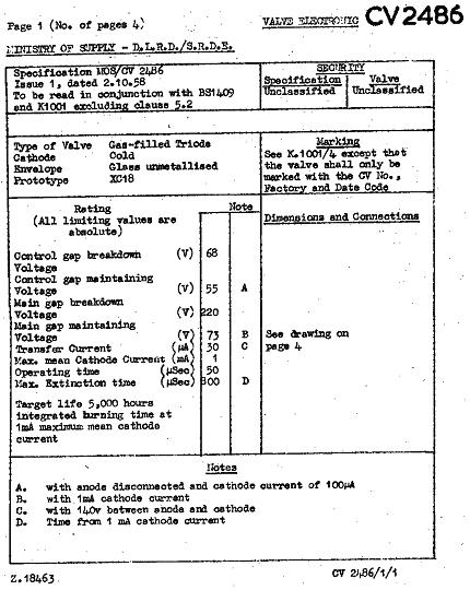
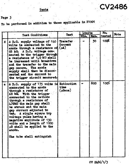
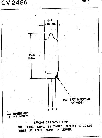
XC18 Datasheet