

A TTL Clock Using Vacuum Fluorescent Tubes
Introduction
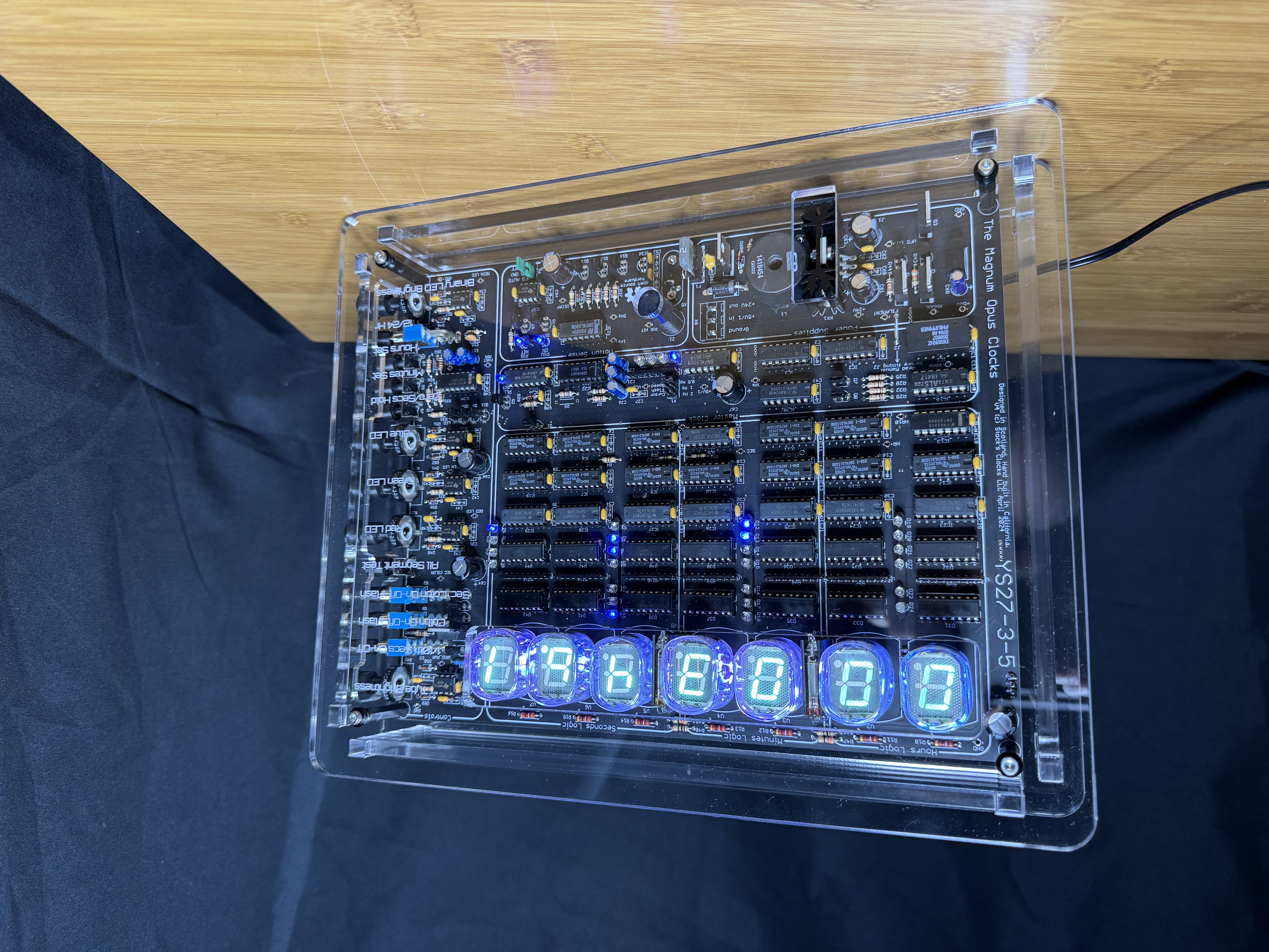
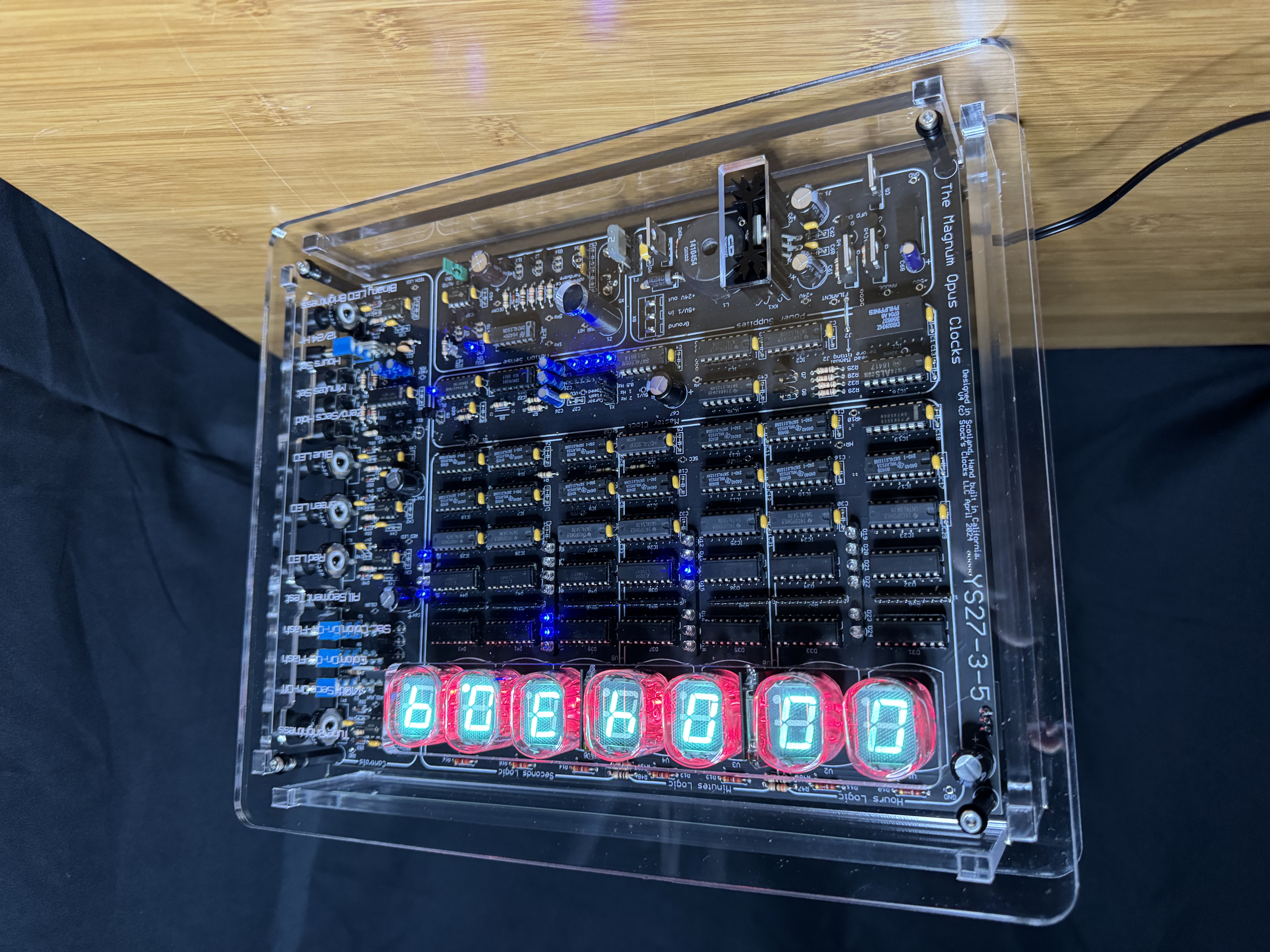
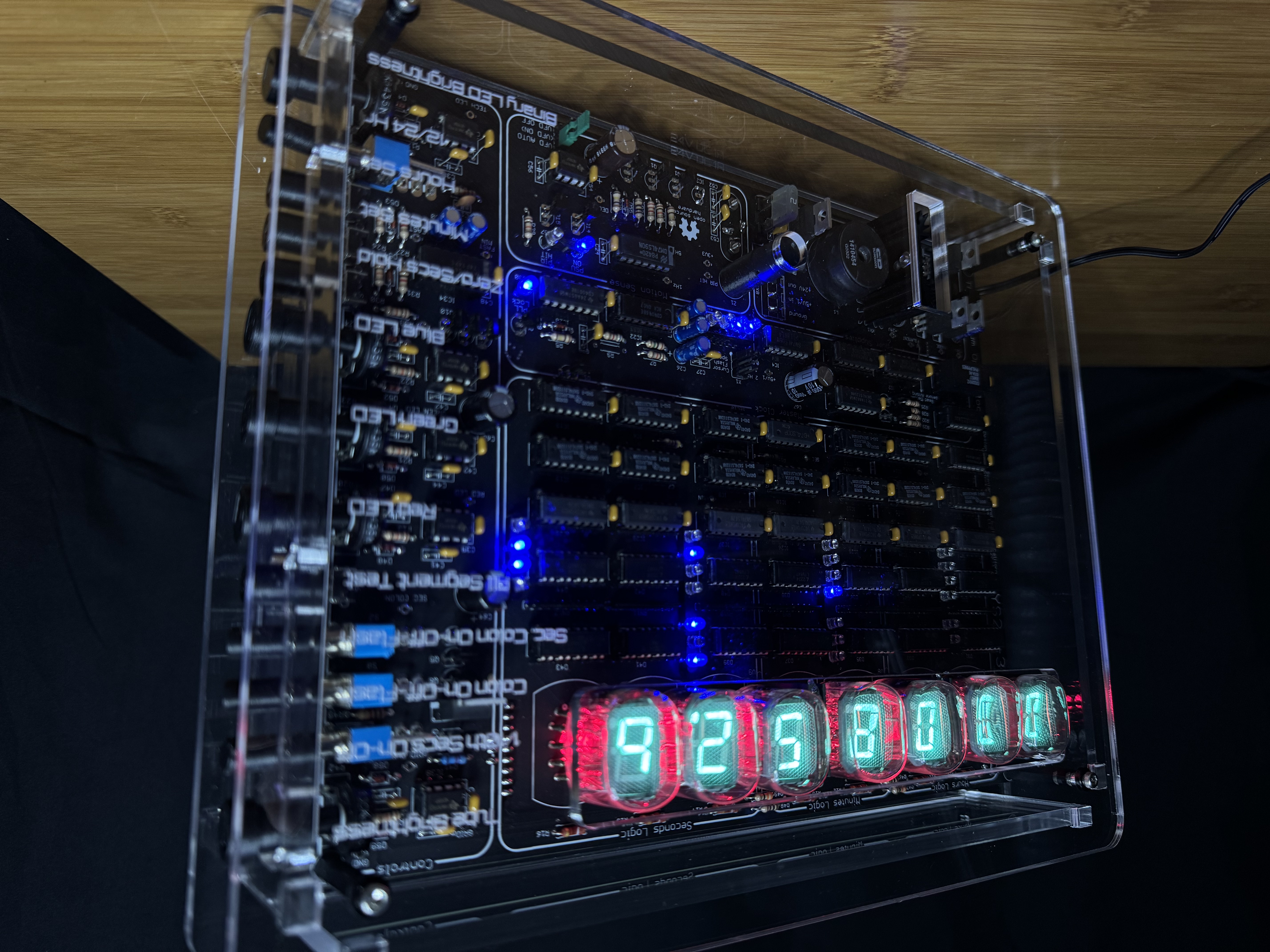
Why? Well, it would appear that I (we) just can't get enough of old display technologies! My friend Nick, he cajoled me into helping design a series of clocks using old display tubes (VFD, nixies and dekatrons) and only TTL logic with about as many knobs, switches and LEDs as possible. It also has one more digit than some may deem necessary. This followed on from my rather remarkable (if I can say so) use of TTL to drive a cathode ray tube, resulting in the SCTTL clock. I think the end result turned out quite nice and it's certain to attract people's attention when on display. The clock also follows some of the design aesthetic of the KoolKlox (also available as a kit from the StocksClocks website here).
Clock Features

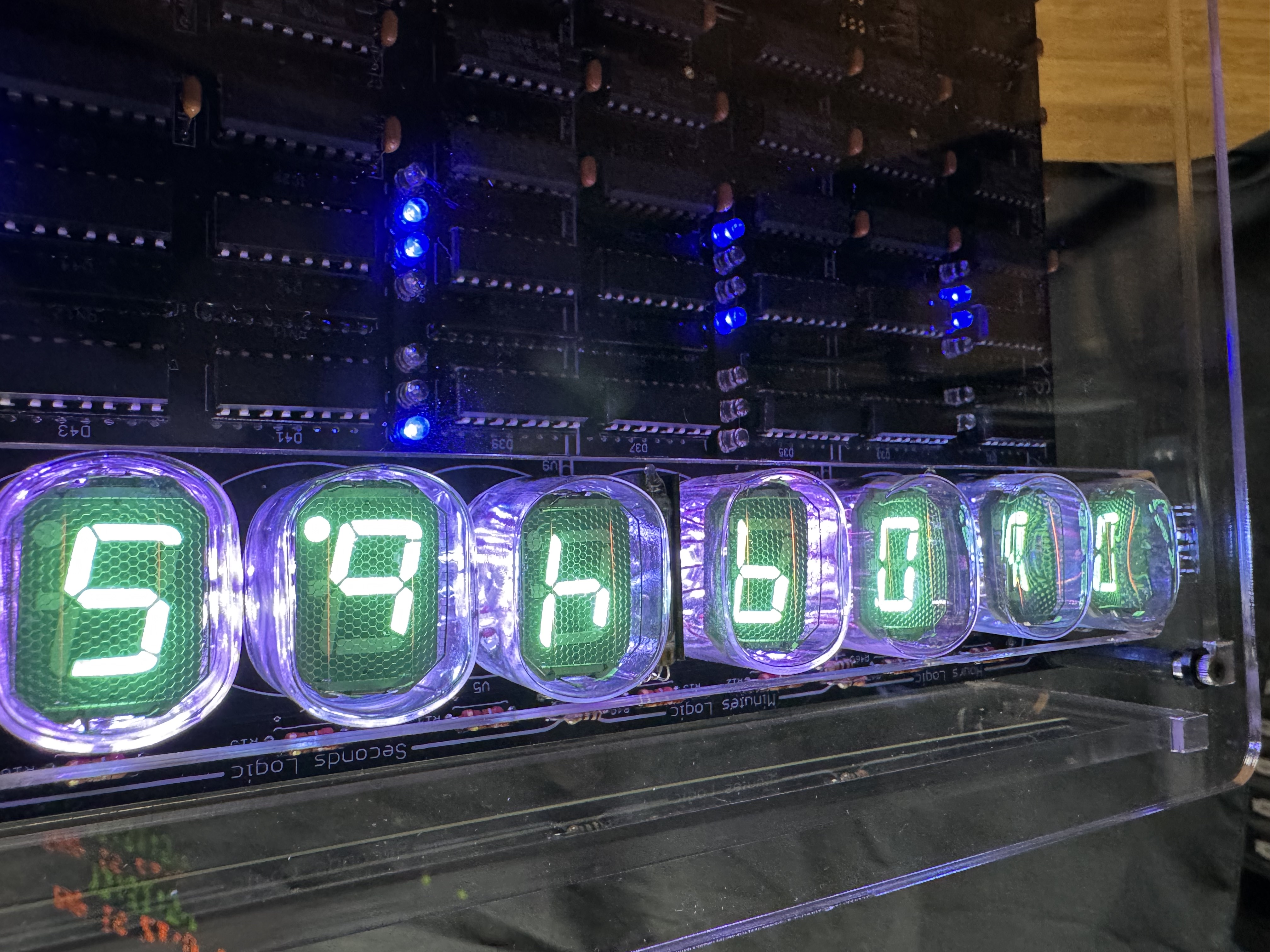
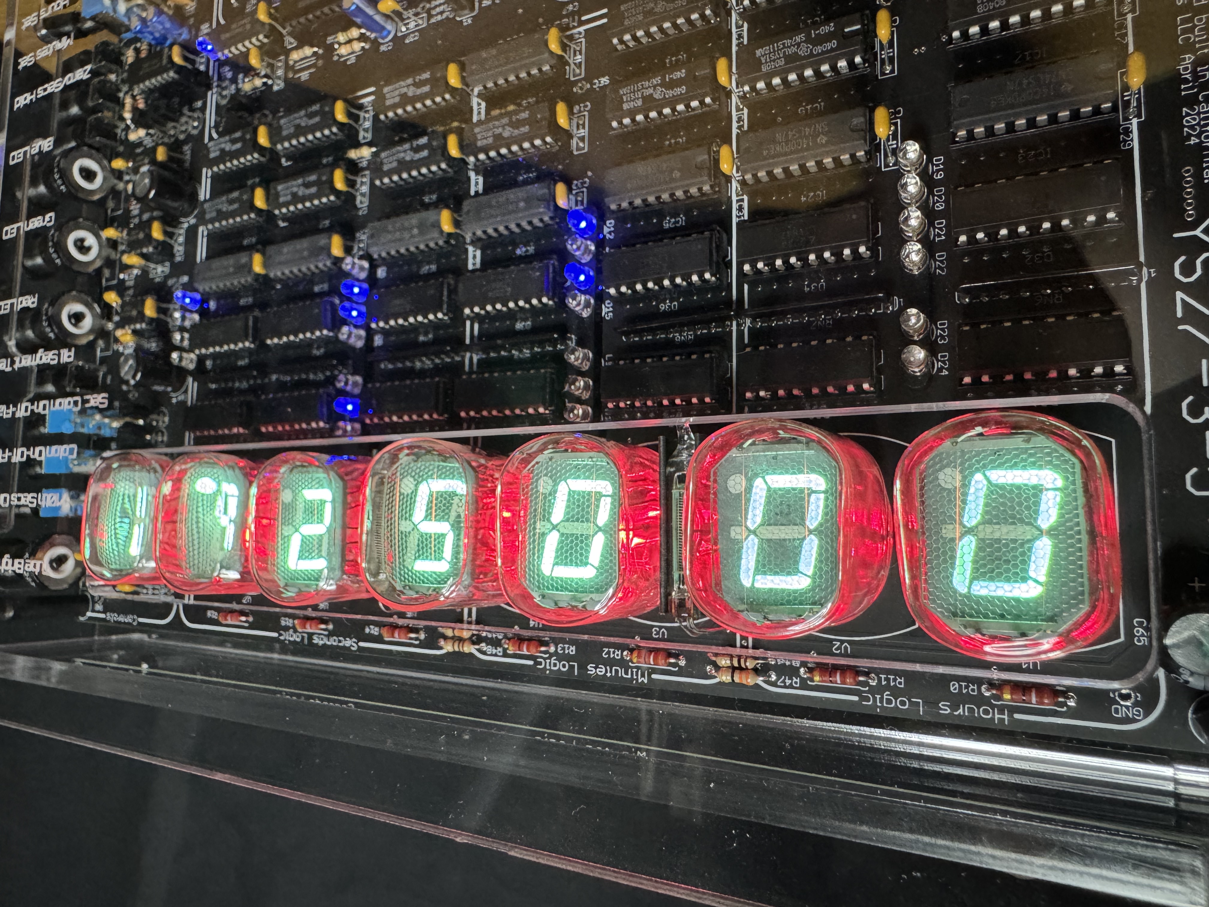
- 7 IV-22 or YS27-3 vacuum fluorescent tubes (VFDs) with a switchable 1/10ths seconds tube
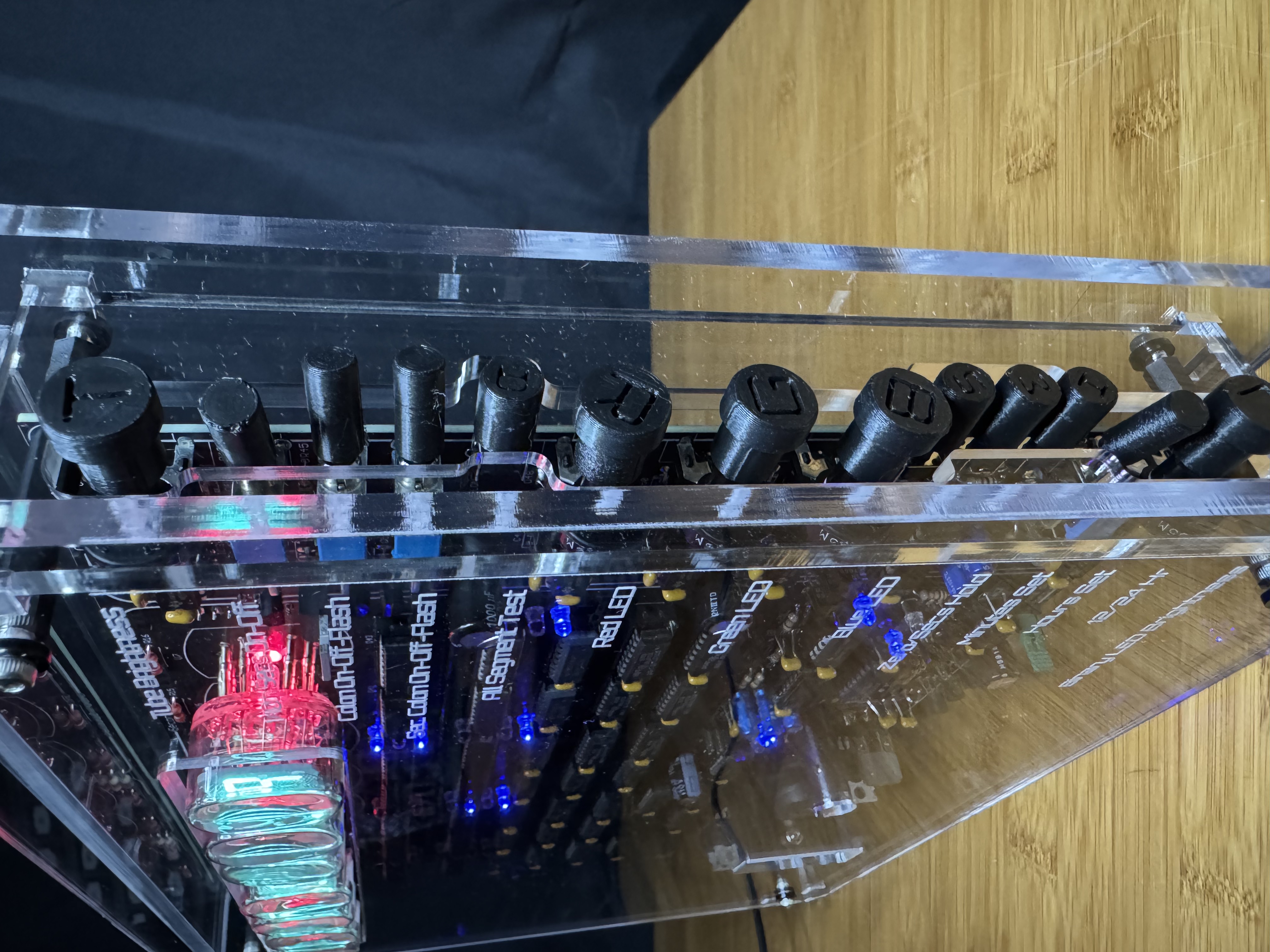
- Tube brightness pot
- Switchable colons using DM160 VFD tubes, with adjustable speed (0.5/1/2 Hz via jumper)
- 12/24 hr switch
- Minutes/Hours set + Seconds hold buttons
- Tube backlighting with adjustable Red, Green and Blue colours
- Binary counting LEDs with adjustable brightness
- Tube "all-segment" test button
- Socketed tubes for easy replacement (if necessary)
- Alternative seconds colon [switchable]
- Optional battery backup to keep time keeping circuit energized during power outages
- PIR (Passive Infra-Red sensor) to turn off the tubes after a period of time (can be defeated with a jumper)
Photo Gallery
How The TTL VFD Clock Works
How a VFD Works

A vacuum fluorescent display (VFD) is a display device once commonly used in consumer electronics equipment such as video cassette recorders, car radios, and microwave ovens.
They operate on the principle of cathodoluminescence, roughly similar to a cathode-ray tube, but operating at much lower voltages. Each VFD tube has a phosphor-coated carbon anode that is bombarded by electrons emitted from the cathode filament. In fact, each VFD is a triode vacuum tube because it also has a mesh control grid.

Unlike liquid crystal displays [LCDs], a VFD emits very bright light with high contrast and can support display elements of various colours. Standard illumination figures for VFDs are around 640 cd/m² with high-brightness VFDs operating at 4,000 cd/m², and experimental units as high as 35,000 cd/m² depending on the drive voltage and its timing. The choice of colour (due to the nature of the phosphor used) and display brightness significantly affect the lifetime of the tubes, which can range from as low as 1,500 hours for a vivid red VFD to 30,000 hours for the more common green ones. Cadmium was commonly used in the phosphors of VFDs in the past, but the current RoHS compliant VFDs have eliminated this metal from their construction, instead using phosphors consisting of a matrix of alkaline earth and very small amounts of group III metals, doped with very small amounts of rare earth metals.
VFDs can display seven-segment numerals, multi-segment alpha-numeric characters or can be made in a dot-matrix format to display different alphanumeric characters and symbols. In practice, there is little limit to the shape of the image that can be displayed: it depends solely on the shape of phosphor on the anode(s). The first VFD was the single bar indicator DM160 by Philips in 1959. The first multi-segment VFD was a 1967 Japanese single-digit, seven-segment device made by Ise Electronics Corporation. The displays became common on calculators and other consumer electronics devices. In the late 1980s hundreds of millions of units were made yearly.

The device consists of a hot cathode (filaments), grids and anodes (phosphor) encased in a glass envelope under high vacuum. The cathode is made up of fine tungsten wires, coated by alkaline earth metal oxides (barium, strontium and calcium oxides), which emit electrons when heated to 650°C by an electric current. These electrons are controlled and diffused by the grids (made using photochemical machining), which are made up of thin (50 micron) stainless steel. If electrons collide with the phosphor-coated anodes, they fluoresce, emitting light. Unlike the orange-glowing cathodes of traditional vacuum tubes, VFD cathodes are efficient emitters at much lower temperatures, and are therefore essentially invisible. The anode consists of a glass plate with electrically conductive traces (each trace is connected to a single indicator segment), which is coated with an insulator, which is then partially etched to create holes which are filled with a conductor like graphite, which in turn is coated with phosphor. This transfers energy from the trace to the segment. The shape of the phosphor will determine the shape of the VFD's segments. The most widely used phosphor is zinc-doped copper-activated zinc oxide, which generates light at a peak wavelength of 505nm.
The cathode wire to which the oxides are applied is made of tungsten or ruthenium-tungsten alloy. The oxides in the cathodes are not stable in air, so they are applied to the cathode as carbonates, the cathodes are assembled into the VFD, and the cathodes are heated by passing a current through them while inside the vacuum of the VFD to convert the carbonates into oxides.

The principle of operation is identical to that of a vacuum tube triode. Electrons can only reach (and "illuminate") a given anode element if both the grid and the anode are at a positive potential with respect to the cathode. Besides brightness, VFDs have the advantages of being rugged, inexpensive, and easily configured to display a wide variety of customized messages, and unlike LCDs, VFDs are not limited by the response time of rearranging liquid crystals and are thus able to function normally in cold, even sub-zero, temperatures, making them ideal for outdoor devices in cold climates. Early on, the main disadvantage of such displays was their use of significantly more power (0.2 watts) than a simple LCD. This was considered a significant drawback for battery-operated equipment like calculators, so VFDs ended up being used mainly in equipment powered by an AC supply or heavy-duty rechargeable batteries.
From the mid-1980s onwards, VFDs were used for applications requiring smaller displays with high brightness specifications, though now the adoption of high-brightness organic light-emitting diodes OLEDs is pushing VFDs out of these markets.
As mentioned previously, the first VFD was the single indication DM160, by Philips. It could easily be driven by transistors, so was aimed at computer applications as it was easier to drive than a neon tube and had longer life than a light bulb. Below you will see that this venerable VFD is used as a colon between the hours, minutes and seconds tubes in the clock.
Suitable Display Tubes
The clock hardware is designed to operate two types of VFDs, the common IV-22 type VFD and the 'less' common Chinese YS27-3 variant

These tubes have the same voltage requirements and roughly similar physical dimensions, the IV-22 having a slightly larger glass envelope. However, they have some minor internal differences. The YS27-3 has an 8th anode which is to the right of the centre horizontal anode. This 8th anode is not used in this clock. The pinouts for the two tubes are different so two tube specific PCBs were designed as an easier solution than using tube specific jumpers or adaptors.
The Intent!
The clock electronics aims at displaying the time using seven 7-segment VFD tubes, separated by a VFD tube as a colon (twice, one between HH and one between MM). LEDs are used to add some bling. In practice we are heading here:
 The clock is divided into 4 major sections to achieve this:
- Time Keeping
- Accurate master oscillator
- Dividers to 1Hz pulses
- 1/10th second counter
- Seconds divider counter
- Minutes divider-counter
- Hours divider-counter
- VFD tubes
- Seven 7 segment VFDs
- Two VFD colon tubes
- Convert the BCD time data to 7 segment illumination
- High voltage anode and grid drivers
- LED Bling
- Power supplies
- +24V VFD anode and grid supply
- +1.32V VFD filament supply
- +24V bling LED power
- +5V digital and clock power
- Room occupancy detection
Documentation
You should look in the "/ VFD Projects / VFD TTL" folder.
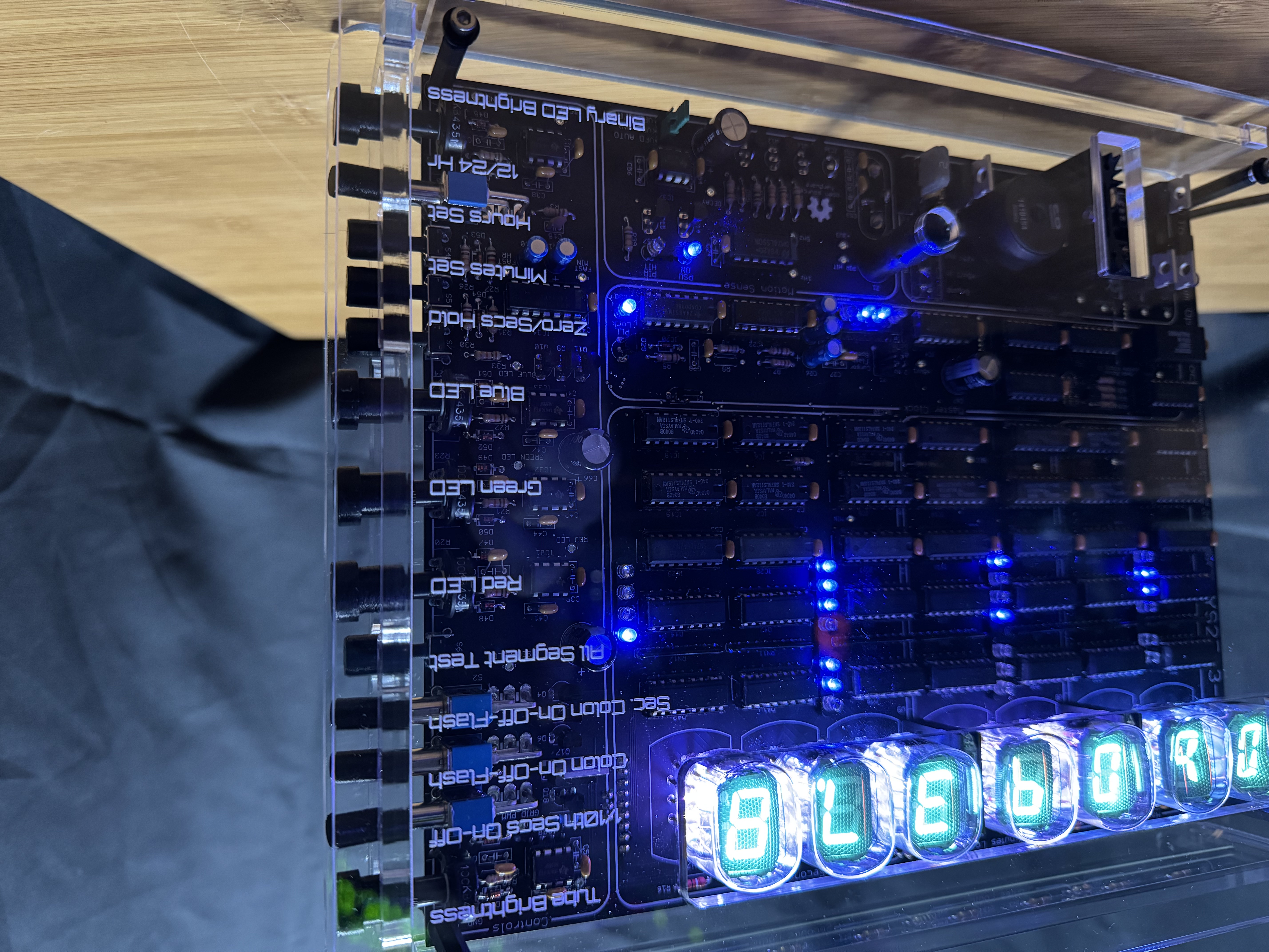
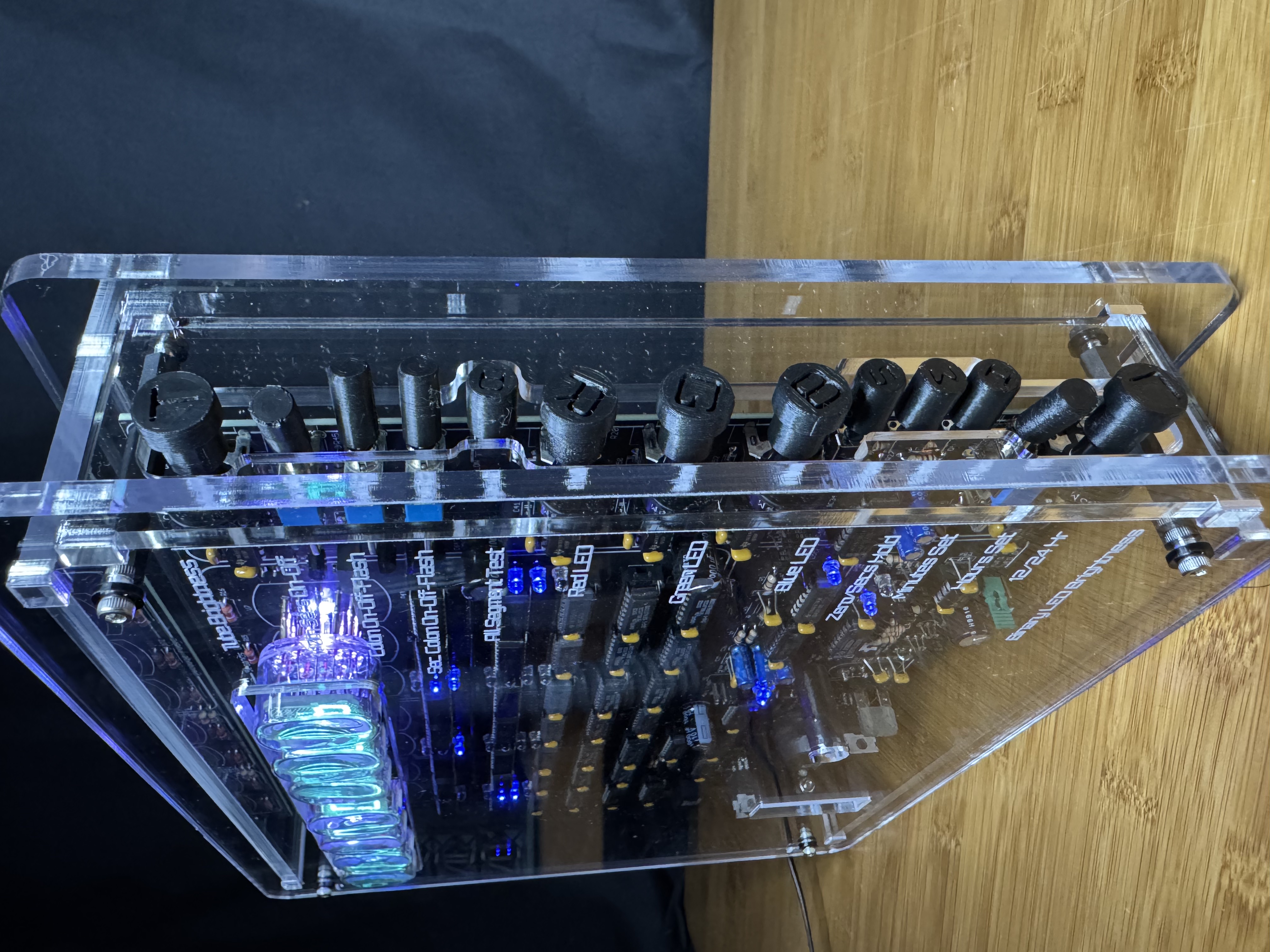
Operational Notes
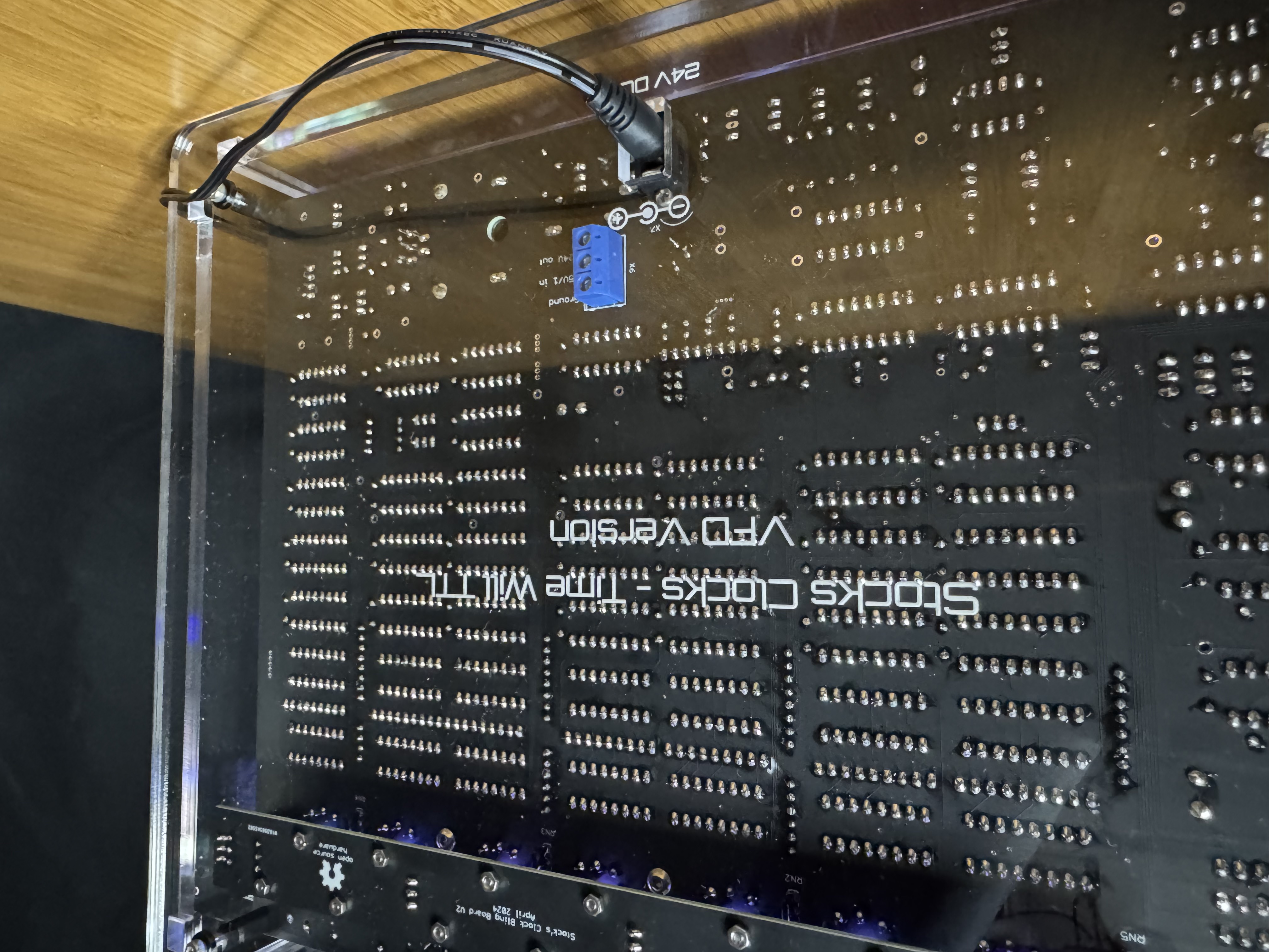
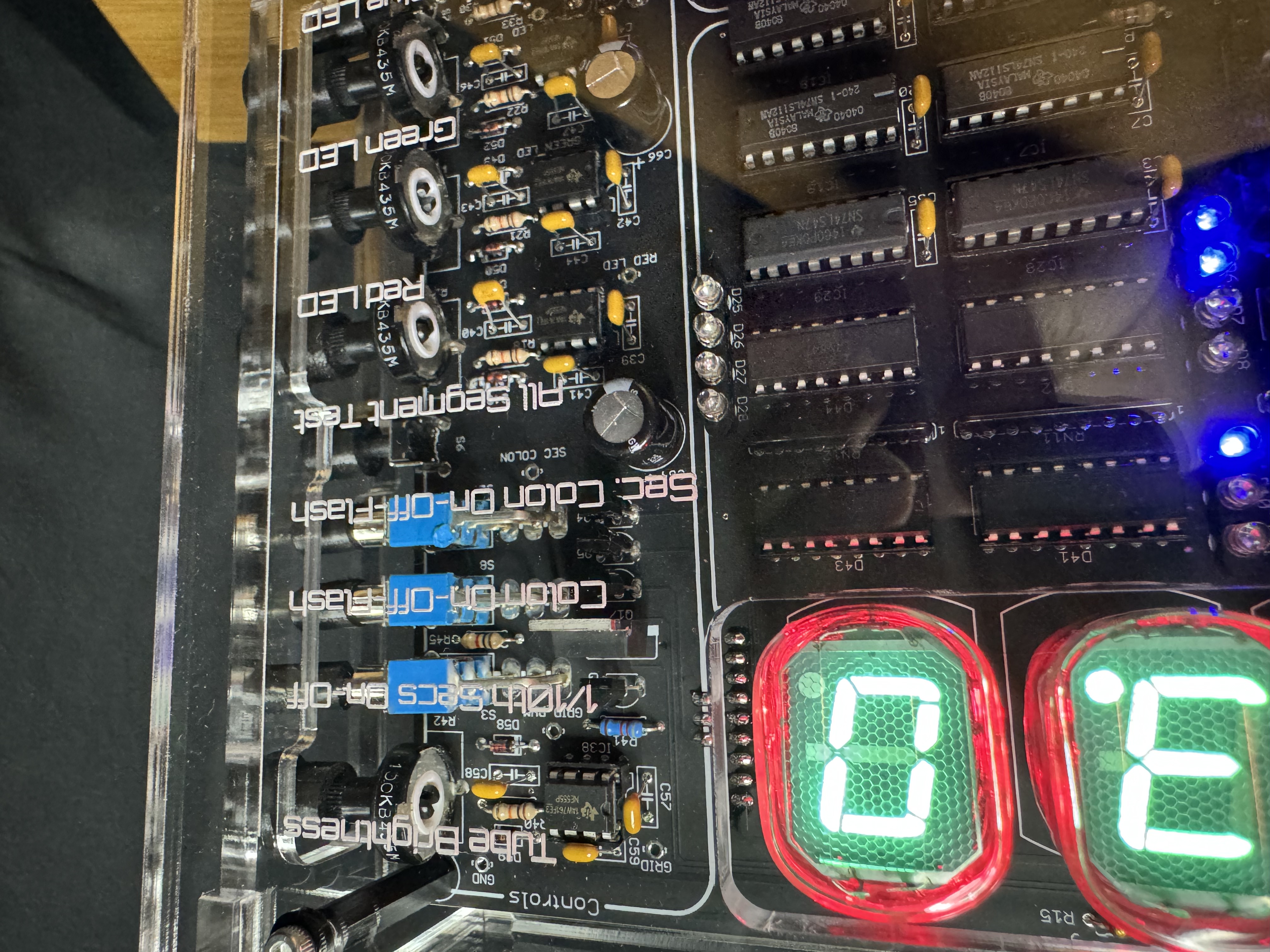
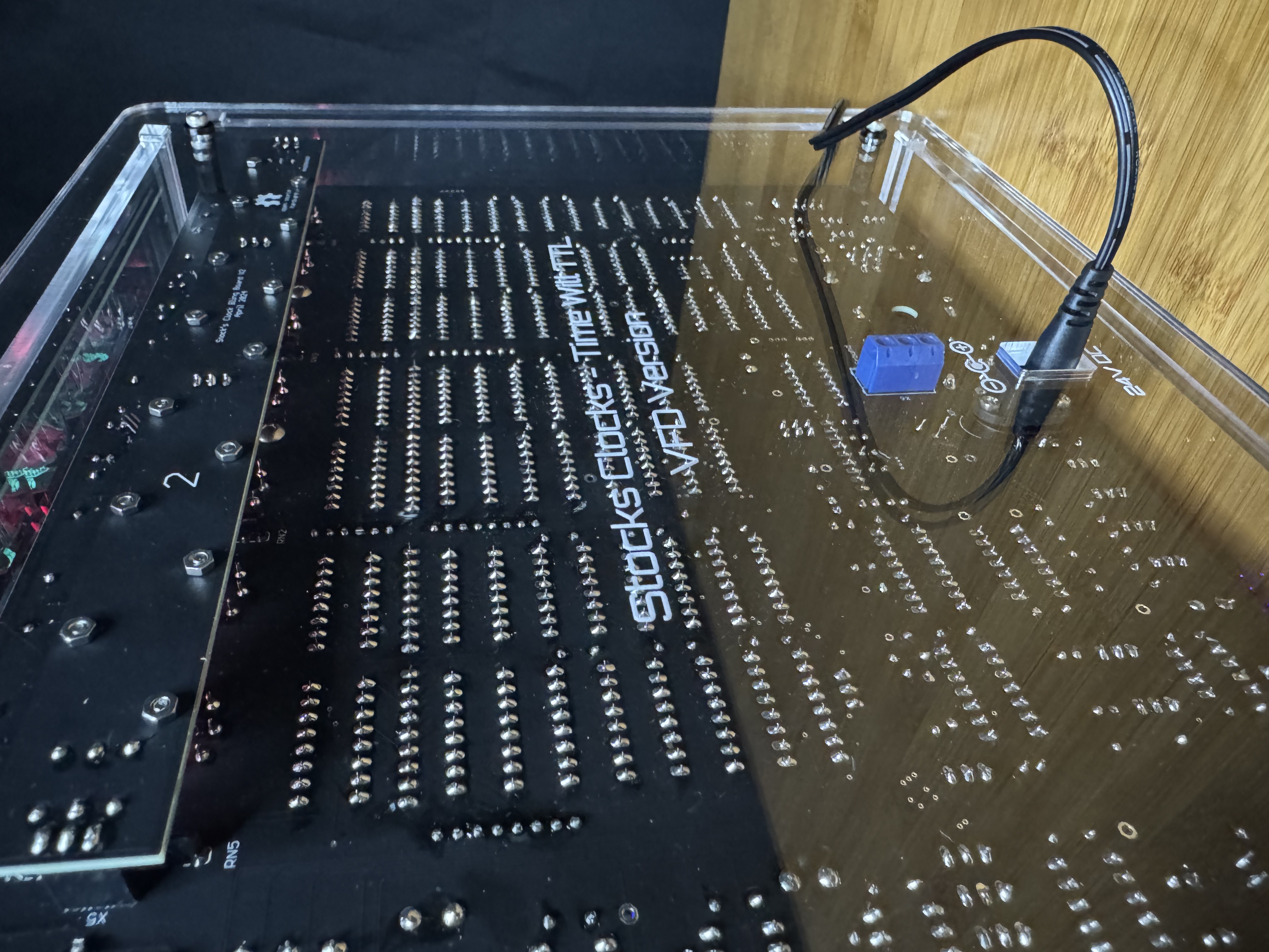
The clock should only be powered by a 24V centre positive DC power supply (5.5/2.1 barrel) with a minimum current supply of 2A. Operating the clock should be fairly obvious, but here's a breakdown of all the twiddly bits…
- Tube Brightness - does what it says!
- 1/10th Secs On-Off - For those that don't like the dance of the 1/10ths of seconds, feel free to turn it off!
- Colon On-Off-Flash - Three-way switch to make the DM160 tubes flash according to the frequency set by the X1 jumper (0.5, 1 or 2 Hz), stay static or turn off.
- Sec. Colon On-Off-Flash - Both the YS27-3 and IV22 tubes contain a decimal point, this switch controls this the same way as the Colon On-Off-Flash switch.
- All Segment Test - Press this button to illuminate all the segments on every VFD tube to test.
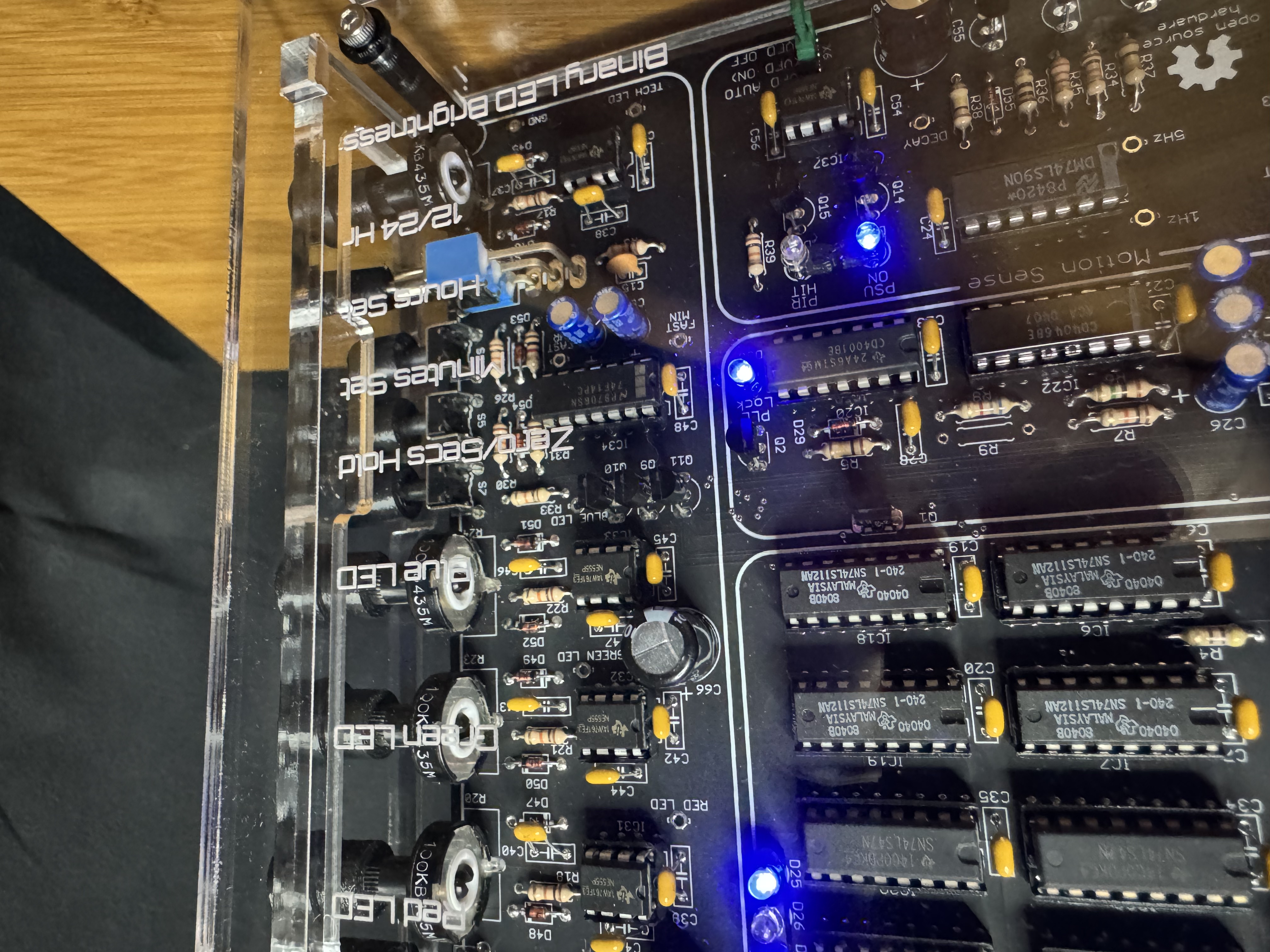
- Adjusting all three of these allows your own colour palette of backlighting!
- Red LED - Controls the brightness of the RED LED.
- Green LED - Controls the brightness of the GREEN LED.
- Blue LED - Controls the brightness of the BLUE LED.
- Zero/Secs Hold - Resets the seconds VFDs to zero and keeps them there until you release the button.
- Minutes Set - Use to set the correct Minutes time.
- Hours Set - Use to set the correct Hours time.
- 12/24 Hr - Toggle between 12 and 24 timekeeping. You may need to cycle through the hours once to reset the hour counters correctly after changing.
- Binary LED Brightness - Controls the brightness of all the LEDs on the clock PCB (Binary counting, PIR and PLL Lock)
Note that this clock will not be as accurate as a GPS or WiFi disciplined device, it's base frequency is derived from a TCXO and as such will drift over time, but that was never the point… :^)
Enjoy!
For Sale
The clock kit and built and tested clocks are only available from Stock's Clocks.