VFD Approximate Clock using a Professional PCB
Introduction
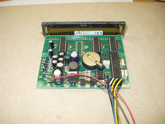
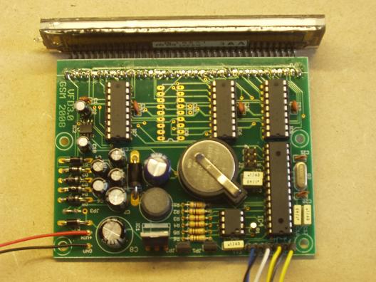
This is the "production" version of the Prototype Approximate Clock.
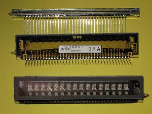
The features remain the same:
- 16 character starburst VFDs (bought on Ebay from Obtainium! (a quick check shows they have none left)
- an atmega168
- A6810 VFD drivers using the SPI port on the mega168
- a DS1307 RTC on the TWI port
- a LM9022 driver to generate the 24VDC required by the VFD and the 4.5VAC filament drive
- wire components and not SMDs and use nothing exotic - all parts should be readily available from UK suppliers (except the VFD of course) and in the end I used one SMD - the LM9022
- PWM to dim the display
- multi-language support (not necessarily simultaneously).
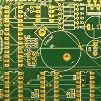
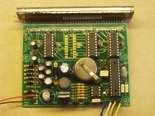
After considerable help from Nick deSmith with the board layout, I eventually placed an
order with Olimex Ltd for a couple of manuafactured boards to build and fully test before looking to a larger
order for gifts and for sale (these are now available).
Schematic and PCB
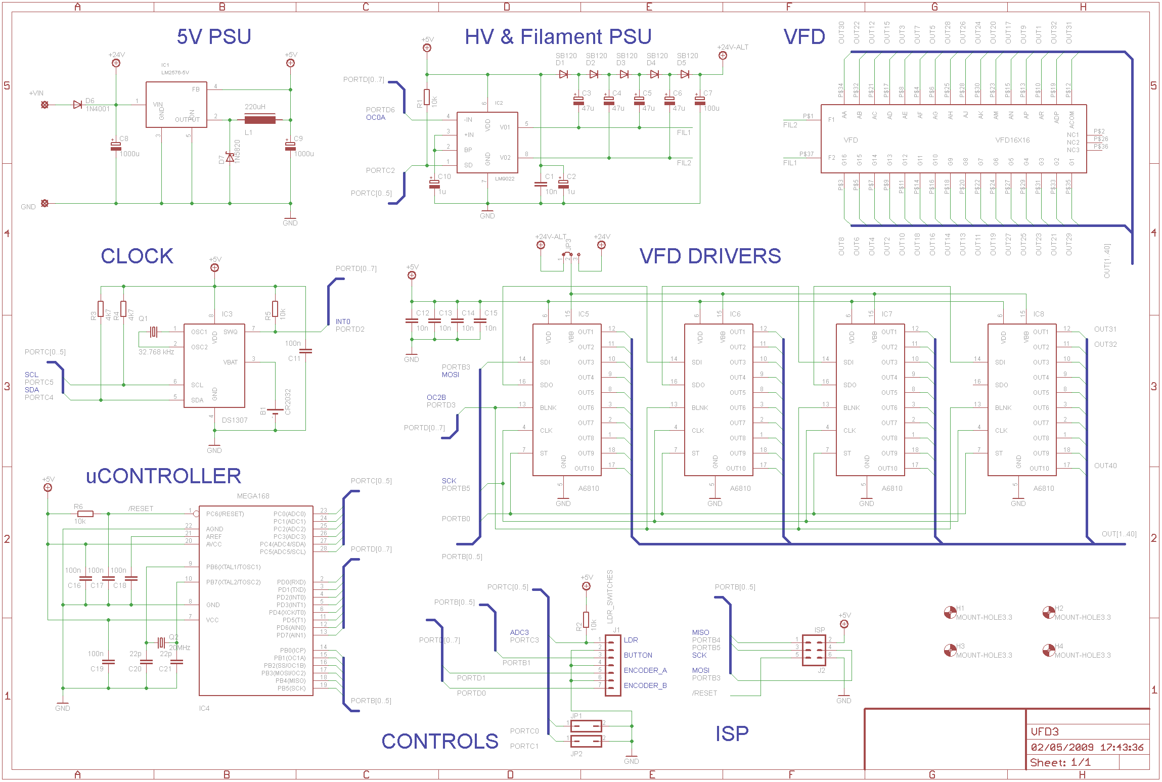
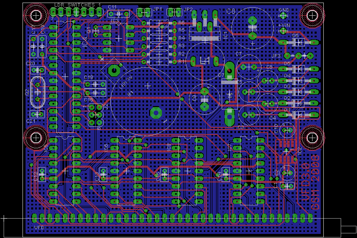
You should look in the "/VFD Projects/Approx Clock 2" folder.
There are two components connected by wires and so not shown on the schematic a NORPS12 LDR to sense light level for setting the display brightness and a rotary encoder with a built in push button (I used an Alps encoder) - see the Parts List below.
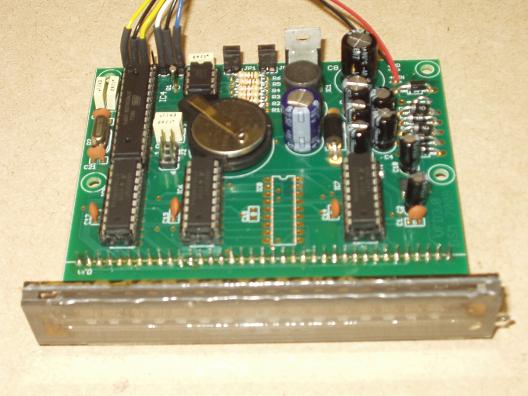
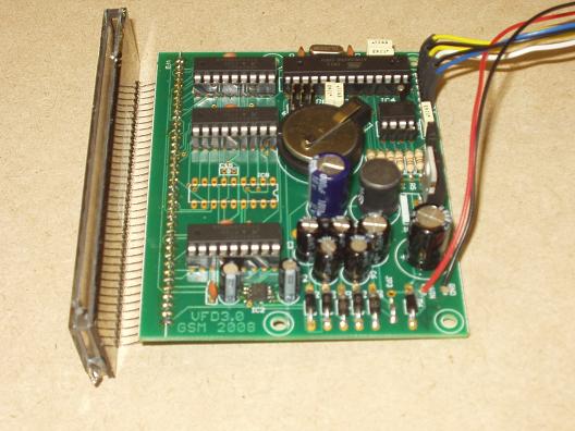
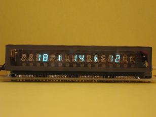
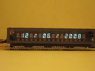
The boards are in the photo gallery below.
Software
The software was written entirely using C and compiled using the CodeVisionAVR compiler. The complete source code is available for download from the dropbox. Beware - C purists beware that my C is perhaps a bit idiosyncratic but I like it. However, I hope you will find the code well commented. I have included the required libraries and you may have to play with the various paths to suit your individual set up. This zip file includes the required fuse settings and compilled hex files.
With help for René Eickhoff I have a German language version available and adding more langauges is fairly straight forward. Croatian, Gaelic, French and Spanish are looking possible.
The clock software has three main modes:
- A scrolling text message displaying the time on as a 12 hour clock, pressing the push button displays a scrolling text message giving the date.
- A static "conventional" digit clock using numbers, pressing the button displays the date using numbers.
- A settings mode where the clock display parameters can be selected using a Clock Menu system. In brief:
- Set Date and Time:
- Set DST - can be off, on (+1hr), automatic to EU rules, automatic to US Federal rules.
- Set year (2000-2099), month, day, hour, minute, second.
- Set Scrolling parameters:
- The Scroll lead-in and lead-out character (including none) as "*" is used in * * * FIVE MINUTES TO EIGHT * * *
- The number of lead in/out character (3 in this example)
- The scroll delay between character shifts in 10mS counts - basically "scroll speed"
- Time Formating:
- HH-MM-SS or HH-MM display
- Select the separator character to use, "-" in this example
- Whether the separator is flashed on and off each second (looks good in HH-MM format)
- Whether spaces are added to use more of the display width: 18 - 16 - 23
- Display the number digital clock in 12 or 24 hour mode: 01:30 or 13:30
- Supress the leading 0 on the hours digits: 09:47 or 9:47
- The "approximate" clock granularity 5, 10 or 15 minutes - the time steps taken between changes
- Date formatting:
- DMY, MDY, YMD formats
- Show the day of week as well on the text display: * * * TUESDAY, JUNE 10, 2008 * * *
- The separator character, spaces selection and leading 0 supression as for the time display above
- PWM dimming controls:
- Automatic or manually set.
- Two parameters for the LDR sensitivity and two more for the VFD PWM limits for fine adjustments.
- Turn off the VFD filament overnight timer (with a wake up function)
- Set Date and Time:
All of these parameters are stored on the NVRAM space on the clock chip and are saved and loaded as required.
Photo Gallery
For Sale
At the time of preparing this web page I have some spare boards and VFDs for sale for 15 GBP for a set (one board, one VFD)
contact me if you are interested. I can also supply the A6810 and LM9022 chips and a programmed
AVR - all for a price of course!
All boards, VFDs, A6810 and LM9022 parts have been sold (sorry)!
Menu
The menu exists as a tree with a "top menu" which is selected using the encoder and then pressing the push button. There are then 6 sub menus and a final "return" back to the top menu. Each sub menu has a sub-sub-menu. When an item to edit is eventually selected, rotating the encoder will show the possible values. Difficult to describe with words, but intuitive to use (IMHO).
| sub-menu | sub-sub-menu | function | range | default |
| 0. DATE&TIME | 0.0 DST MODE | Allows automatic adjustment for DST |
|
2 |
| 0.1 YEAR | Adjust clock year | 2000-2099 | 2000 | |
| 0.2 MONTH | Adjust clock month | 1-12 | 1 | |
| 0.3 DAY | Adjust clock day | 1-28,29,30,31 depends on month |
1 | |
| 0.4 HOUR | Adjust clock hours | 0-23 | 0 | |
| 0.5 MINUTE | Adjust clock minutes | 0-59 | 0 | |
| 0.6 SECOND | Adjust clock seconds | 0-59 | 0 | |
| 0.7 ADJUST | This number of seconds is added (or subtracted) from the time each Sunday midnight - use to fine tune clock accuracy | ±120 seconds | 0 | |
| 0.8 RETURN | Back to sub-menu | |||
| 1. SCROLLING | 1.0 CHARACTER | Character use to to prefix and postfix the scrolling display e.g. = in = = = IT'S ABOUT SIX O'CLOCK = = = |
Any valid character | * |
| 1.1 COUNT | The number of prefix and post fix characters to use, such as 3 in the above example | 0 - 20 | 3 | |
| 1.2 TEMPO | Adjust the speed of the scrolling text, low number = fast, high number = slow | 1 - 255 | 30 | |
| 1.3 DATE EVERY | Show the time this count and then show the date once | 0 - 20 0 = never |
5 | |
| 1.4 RETURN | Back to sub-menu | |||
| 2. TIME | 2.0 CHARACTER | Y = HHMM format N = HHMMSS format |
N - Y | N |
| 2.1 SEPARATOR | Separator between HHMM and MMSS e.g. 23 = 01 = 56 |
Any valid chanarcter | = | |
| 2.2 BLINK | The separator can blink on and off every second | N - character is steady Y - character is blinking |
N | |
| 2.3 SPACES | Are the time numbers and separator characters spaced out e.g. 23 = 01 = 56 -or- 23=01=56 |
N - no spaces inserted Y - spaces are inserted |
Y | |
| 2.4 12 HOUR | clock is either 24 hour (0 - 23) or 12 hour (1 - 12) | N - 24 hour clock Y - 12 hour clock |
N | |
| 2.5 LEADING 0 | The leading 0 on the hour can be omitted 03 = 01 = 56 -or- 3 = 01 = 56 |
N - omit a leading 0 Y - show leading 0 |
Y | |
| 2.6 GRANULARITY | The approximation of time into 5 minute, 10 minute or 15 minute chunks for the scrolling display |
|
0 | |
| 2.7 RETURN | Back to sub-menu | |||
| 3. DATE | 3.0 FORMAT | Select the format for the date e.g. 23 May 2009 -or- May 23, 2009 -or- 2009 May 23 in the scrolling mode and 23/05/2009 -or- 05/23/2009 -or- 2009/05/23 in the non-scrolling mode |
|
0 |
| 3.1 DOW | Select if the day of the week will preceed the date e.g. FRIDAY, 10 APRIL 2009 (etc) | N - no DOW Y - insert DOW |
Y | |
| 3.2 SEPARATOR | Select the separator for the non-scrolling date e.g. / in the examples above | Any valid character | / | |
| 3.3 SPACES | Are the date numbers and separator spaced out e.g. 23/05/2009 -or- 23 / 05 / 2009 |
N - no spaces inserted Y - spaces inserted |
Y | |
| 3.4 LEADING 0 | The leading 0 on the day and month can be omitted 03/01/2009 -or- 3/1 /2009 |
N - omit a leading 0 Y - show leading 0 |
Y | |
| 3.5 RETURN | Back to sub-menu | |||
| 4. DIMMING | 4.0 UTILITY | display the current value from the LDR ADC. Will show a lower number in a bright environment (300 typically) and a high value in a dark room (1000 typically) | not a menu | |
| 4.1 AUTO | Select if dimming control is manual or automatic (depends on room light level) | N - manual Y - auto |
Y | |
| 4.2 MANUAL PWM | If manual control is set then the display brightness can be adjusted; low number gives a darker display (below about 40 the display can break up or disappear entirely) | 0 - 255 | 255 | |
| 4.3 DARK ADC | The LDR ADC for a dark room (use the utility menu 4.0. to determine the value - not critica | 0 - LIGHT ADC | 300 | |
| 4.4 LIGHT ADC | The LDR ADC for a bright room | DARK ADC - 1023 | 1000 | |
| 4.5 DIM PWM | The display brightness that will be used in a dark room | 0 - BRIGHT PWM | 40 | |
| 4.6 BRIGHT PWM | The display brihtness that will be used in a bright room | DIM PWM - 255 | 255 | |
| 4.7 BLANK START | Time in decimal hours (e.g. 23.5 is 23:30) that the display will shutdown | 0.0 - 23.9 | 23.5 | |
| 4.8 BLANK END | Time in decimal hours (e.g. 23.5 is 23:30) that the display will start up again (if start is set equal to end then the display will not shutdown) | 0.0 - 23.9 | 5.5 | |
| 4.9 WAKE UP | If the encoder is moved or pressed the display will wakeup for this number of minutes | 0 - 240 | 1 | |
| 4.10 RETURN | Back to sub-menu | |||
| 5. RESET | Reset to default settings (except clock date and time) | Y - Restore N - Don't restore |
N | |
| 6. RETURN | Back to top menu selector | |||
Parts List
Although all listed here, many items were bought on Ebay or were selected as I already had them to hand for instance the SB160 diodes could be replaced by many other diodes with a lower voltage rating. Obviously the component sizes and shapes only become important if you are going to reproduce the Eagle PCB layout without change or if you are going to use the available PCB. Some components are critical, most of the ICs and crystals for example. The capacitors in the power supply a closely spaced so the table below includes the required dimensions. The microcontroller expects the pulse series for the encoder used (sequence and timing) substituting a very different encoder might require code changes. Otherwise most of the components can be substituted with other types and ratings.
The Mouser and Digi-Key Parts List can be downloaded and an Excel Spreadsheet from the dropbox (with thanks to Mark Kaufman).
| Parts | Value | Farnell Code | Rapid Code | Digi-Key Code | Mouser Code | Dimensions |
| B1 | CR2032 Cell CR2032 Holder |
18-0490 18-0498 |
N189-ND BS-7-ND |
658-CR2032 122-2520-GR |
flat style 24mm diameter two pin - 20 mm spaced |
|
| C1, C12-C15 (see note 2) |
10n ceramic |
08-0232 | 399-4150-ND | 594-K103M15X7RF53H6 | 2.5mm leg spacing | |
| C2, C10 | 1u 63V radial electrolytic |
11-0205 | P13468-ND | 140-XRL63V1.0-RC | 2 mm lead spacing 5mm can diameter |
|
| C3-C6 (see note 1) |
47u 35V radial electrolytic |
11-0345 | P11232-ND | 647-UPB1V470MED | 2.5 mm lead spacing 6.3 mm can diameter |
|
| C7 (see note 1) |
100u 35V radial electrolytic |
11-0350 | P10294-ND | 647-URZ1V101MPD1TA | 3.5 mm lead spacing 8 mm can diameter |
|
| C8 | 1000u 35V radial electrolytic |
11-0760 | P10305-ND | 647-UVZ1V102MHD | 5 mm lead spacing 13 mm can diameter |
|
| C9 | 1000u 10V radial electrolytic |
11-0315 | P10225-ND | 647-UVZ1A102MPD | 5 mm lead spacing 10 mm can diameter |
|
| C11,C16-C19 | 100n polyester | 10-3260 | 495-2465-ND | 80-R82DC3100AA50M | 5mm lead spacing | |
| C20, C21 | 22p ceramic | 08-0046 | 495-1004-1-ND | 140-50N2-220J-RC | 2.5 mm lead spacing | |
| L1 | 220 uH radial minature |
88-1037 | 811-1316-ND | 580-18R224C | 7.2 mm lead spacing 13 mm diameter |
|
| D1 - D5 (see note 1) |
SB160 | 47-5316 | MBR160-ND | 863-MBR160G | ||
| D6 (see note 6) |
IN4001 | 47-3130 | 1N4001GDICT-ND | 583-1N4001-B | ||
| D7 | IN5820 | 47-2546 | 1N5820-TPMSCT-ND | 844-1N5820 | ||
| Encoder and switch | Alps EC12E2424407 | 1520813 | 688-EC12E2424407 | |||
| IC1 (see note 3) |
LM2576-5 | 1564682 | 82-0664 | LM2576T-5.0-ND | 863-LM2576T-005G | |
| IC2 | LM9022 (SMD) | 1286933 | LM9022M-ND | |||
| IC3 | DS1307 | 1188042 | 82-0567 | DS1307+-ND | ||
| IC4 | ATMEGA168-20 | 9171207 | 73-4276 | ATMEGA168-20PU-ND | 556-ATMEGA168-20PU | |
| IC5-8 (see note 2) |
A6810 | 1193489 | 620-1092-ND | |||
| Q1 | 32.768 kHz crystal watch, radial |
90-3052 | 300-8303-ND | 695-CFS206-327KF-U | 2.5 mm lead spacing | |
| Q2 | 20MHz crystal HC49U |
1469646 | 90-1084 | 300-8507-ND | 695-HC49US-20-U | |
| LDR (see note 5) |
NORPS12 | 58-0132 | PDV-P9203-ND | |||
| R1, R2, R5, R6 | 10k 0.25W carbon | 63-2344 | 10KQBK-ND | 291-10K-RC | ||
| R3, R4 | 4k7 0.25W carbon | 63-2340 | 4.7KQBK-ND | |||
| X1 | VFD | see above | ||||
| 4 off (see note 2) |
DIL18 sockets | 22-0165 | ED3318-ND | 535-18-3518-10 | ||
| 1 off | DIL28-3 socket | 22-0175 | ED3328-ND | 535-28-3518-10 | ||
| 1 off | DIL8 socket | 22-0150 | ED3308-ND | 535-08-3518-10 | ||
| JP1, JP2 (see note 7) |
pin header jumper | |||||
| J1 switch, LDR and encoder connection | 7 pin header or wiring | |||||
| J2 ISP connector |
6 way (see note 4) |
|||||
Notes:
- If a 24VDC power supply is used then D1 - D5, C3 - C7 can be omitted. JP3 must be set accordingly.
- The current software version does not address the dot or comma display so IC8 and C15 can be omitted (it would not hurt to fit the socket and C15 as a low cost compromise).
- DC input voltage can be anywhere in the range 12 VDC to 40VDC, higher if the high voltage version of IC1 is used.
- ISP connector is arranged as a standard Atmel 6 pin - pins 1 and 6 are marked for correct orientation.
- The LDR can be omitted and the display brightness set manually.
- This diode is for accidental reverse polarity protection and is not intended as a rectifier.
- The current software does not use these jumpers, so they can both be omitted.
