
Introduction

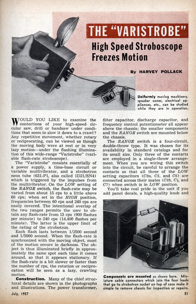
A good friend of mine gave me a large box of valves when cleaing out his loft. Many were WW2 valves such as the pillar box EF50 and acorn valves. In the box was an interesting looking discharge valve of some sort with only "CV2…" remaining of the label. Some time rummaging through valve collections suggested that it is a CV220 which is listed as being equivalent to the NSP1. This class of neon filled glow lamp are generally called a 'Strobotron' or 'Neonstron' and its application is as a stroboscope tube. This type of neon filled stroboscope tube was replaced by xenon gas filled tubes which have the advantage of being brighter and emiting white light.
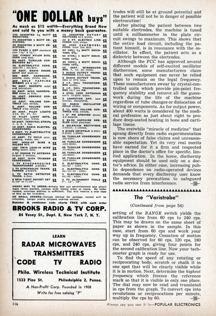
Further rummaging and a July 1955 design from the magazine Popular Electronics. This looked like something fun to build so I started to collect components for this the all-valve 1955 design.
Before I continue … a big thank you to my friend Mike!
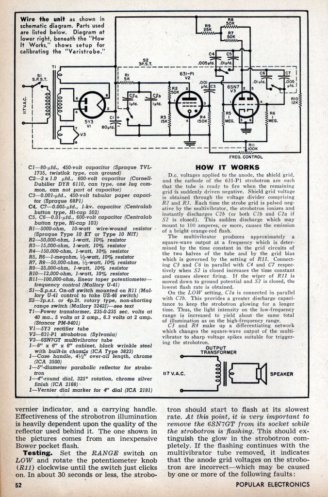
My schematic
Pages from the original 1955 design are in an Annex I below (as an exercise, you might like to work out how the power supply operates as originally printed).

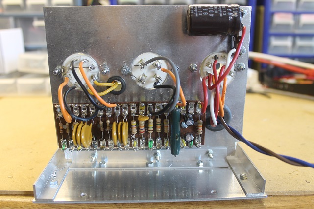
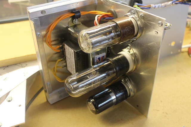
Some adaptation to modern components values was needed. A 50k resistor became 47k, a 0.005μF capacitor became 4n7 and so on. But I used the same rectifier (5Y3) and double triode (6SN7GT). The transformer is a general purpose one aimed primarily for all-valve audio preamplifiers. The rest of the components are standard and easily obtained from suppliers or ebay. During construction it became quiet clear how small the modern electrolytic capacitors are compared with the illustrations in the magazine.
The only real modification I made to the design was to add a socket to output the oscillator square wave attenuated to about 3V peak so I could measure the frequency (using a not-so-1950's frequency meter).
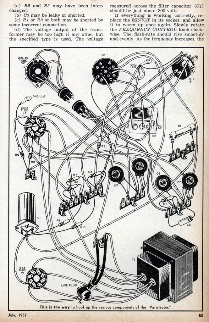
Physical Build
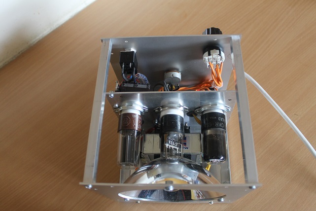
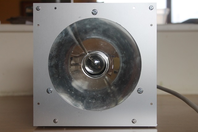
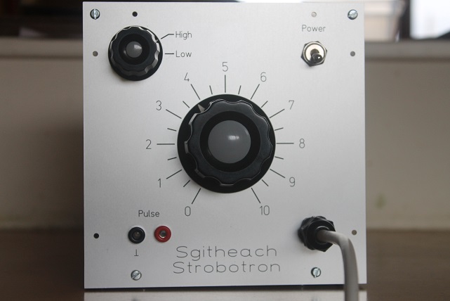
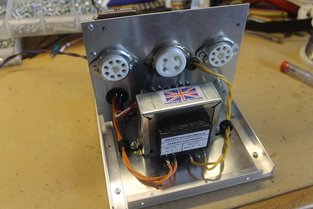
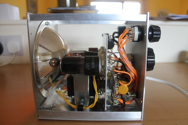
I constructed a simple metal case using sheet, angle and square section aluminium. The front and back panels are laser cut and engraved (oooops, again not-so-1950's but the equivalent mechanical milling and engraving would have been possible in the 1950's to give a similar appearance). The case size was made as small as I could conveniently make it and the transformer located centrally and low down to give a steady feel and a low centre of gravity. Luck on ebay provided the 125mm diameter parabolic reflector (from some sort of light fitting). The following gallery illustrates the construction.

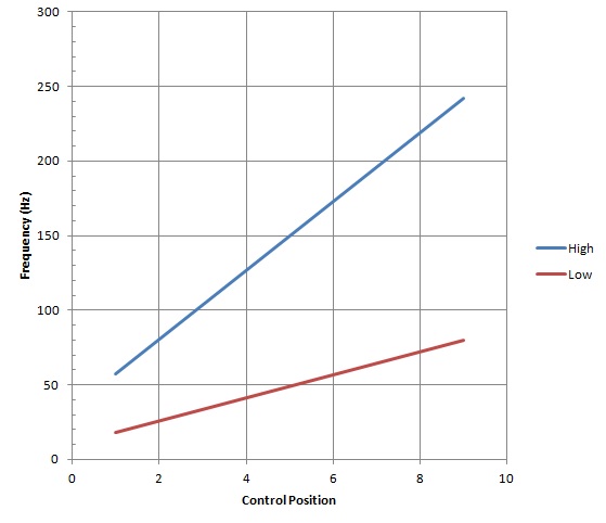
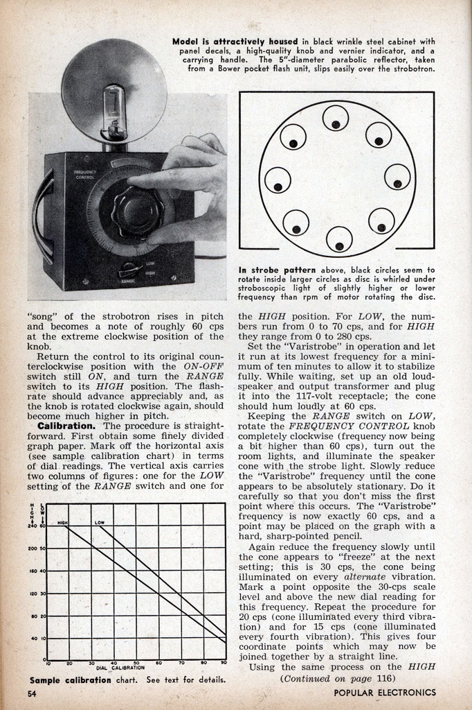
Calibration
I cheated and used a frequency meter to calibrate the strobotron:
Annex I July 1955 Practical Electronics article
Annex II D.M. Neale says
In Chapter 6 of Cold Cathode Tube Circuit Design by D.M. Neale (D.Van Nostrand Inc 1964) it says:
CHAPTER SIX
Arc Discharge Tubes
If a cold cathode tube is connected directly in parallel with a charged capacitor, breakdown of the anode-cathode gap allows the discharge
to carry a current which is limited only by the 'internal resistance' of the discharge and by resistance and inductance of the leads from capacitor
to tube or in the capacitor itself. It follows that, unless the capacitance is kept so small that it discharges before the tube has become heavily
ionized, the discharge will pass rapidly through the normal and abnormal glow regions to become an arc (Fig. 2.2).

Fig. 2.2. Typical voltage-current characteristics of gas discharge.
The discharge then centres on a small spot on the cathode and the high current density (100-1,000 A/cm²) leads to rapid destruction of a cathode not suited to this mode of operation.Three classes of cold cathode arc tubes are discussed here:
- Stroboscopic flash and switching tubes provided with internal electrodes permitting triggering from low-voltage, low-energy pulses.
- …
Arc Discharge Tetrodes
In 1928 Steinert described the first use of a neon tube to provide a high-resolution stroboscope with no moving parts. A saturated-core transformer connected to the supply mains generated a peaked wave-form which was applied to a neon diode and 'tuning capacitor' connected in shunt across the secondary winding. On each half-cycle of the supply the lamp produced a flash of duration estimated at 20 μsec.
Four years later, Quarles described a neon-flash stroboscope with many features characteristic of modern devices, but using the KU-610 hot cathode tube. This grid-controlled tube provided a 0.3 μsec flash in response to triggering pulses from a multivibrator or electrical contacts.
The work of Edgerton, Germeshausen, and Grier led to the cold cathode neon tetrode exemplified in the Sylvania 'Strobotron' and Ferranti 'Neostron'. Hilliard describes the Sylvania lD2l/631Pl illustrated in Fig. 6.1. Between anode and cathode lie a cylindrical

Fig. 6.1. Electrode structure of arc tetrode (Sylvania lD2l/63lPl).
graphite outer grid, G2, and, nearer the cathode, a wire probe inner grid, G1. The control characteristics of the tube are complicated by the number of variables involved: given suitable applied voltage, a discharge may be initiated in either direction between any pair of electrodes.

Fig. 6.2. Ignition characteristic of arc tetrode. Triggering is usually effected by breakdown between G2 and G1.
A study of the triggering characteristics in Fig. 6.2, however, shows that the anode voltage has little effect on the critical grid potentials for the normal mode of operation. This comprises holding G2 positive and applying a negative-going pulse to G1. A pulse of -30V will suffice with a positive bias of about 100 V on G2. The triggering characteristics tend to change during the life of the tube, however, and it is therefore preferable to bias less critically and apply a much larger trigger pulse. If this is generated by a trigger tube operating in the self-quenching mode this may easily be of the order of 100V.
With a negative-going pulse on G1, breakdown between anode and cathode follows after a formative delay which, though dependent on anode voltage and, to some extent, on pulse amplitude, is independent of pulse duration. Feinberg has studied the performance of neon-filled and argon-filled tubes with pulses of both polarities. With positive pulses on G1 he finds anode breakdown tends to occur at a fixed time after the termination of the trigger pulse. This is not surprising, since with positive pulses the field between G1 and G2 is in a direction to oppose the diffusion of electrons into the anode-G2 gap. With increasing anode voltage this relation expires at progressively shorter pulse durations. Feinberg was able to produce a controlled delay of 10-400 μsec.
Once an anode-cathode breakdown is established, it is important that the cathode current be allowed to rise rapidly to a sufficiently high value (≈5 A) to produce an intense cathode spot and so allow the discharge to become an arc. To this end, a cathode is used containing caesium. The capacitor discharges rapidly through the arc until a charge of only 20 V remains. At this voltage the discharge normally extinguishes. As the arc impedance is low, excessive series inductance due to long leads, for example - can lead to voltage backswing and inverse conduction. The anode then assumes the role of cathode, and severe sputtering may result. This will produce blackening of the envelope and some clean-up of the gas. Series inductance should therefore be minimized (e.g. by shortening and twisting leads) or, if it is unavoidable, sufficient circuit resistance should be introduced to provide critical damping.

Fig. 6.3. Free-running stroboscope.
A simple free-running stroboscope may be constructed to the circuit of Fig. 6.3. In operation such a stroboscope may show some 'jitter' due to its sensitivity to changes in supply voltage and tube characteristics. It is accordingly preferable to synchronize the stroboscope tube by applying negative-going pulses to G1 from a separate multivibrator or blocking oscillator.
In addition to the neon-filled tubes, similar tubes are available with other gas-fillings (e.g. argon) better suited to photographic application.