Introduction
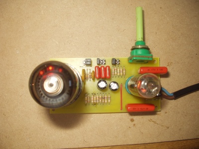
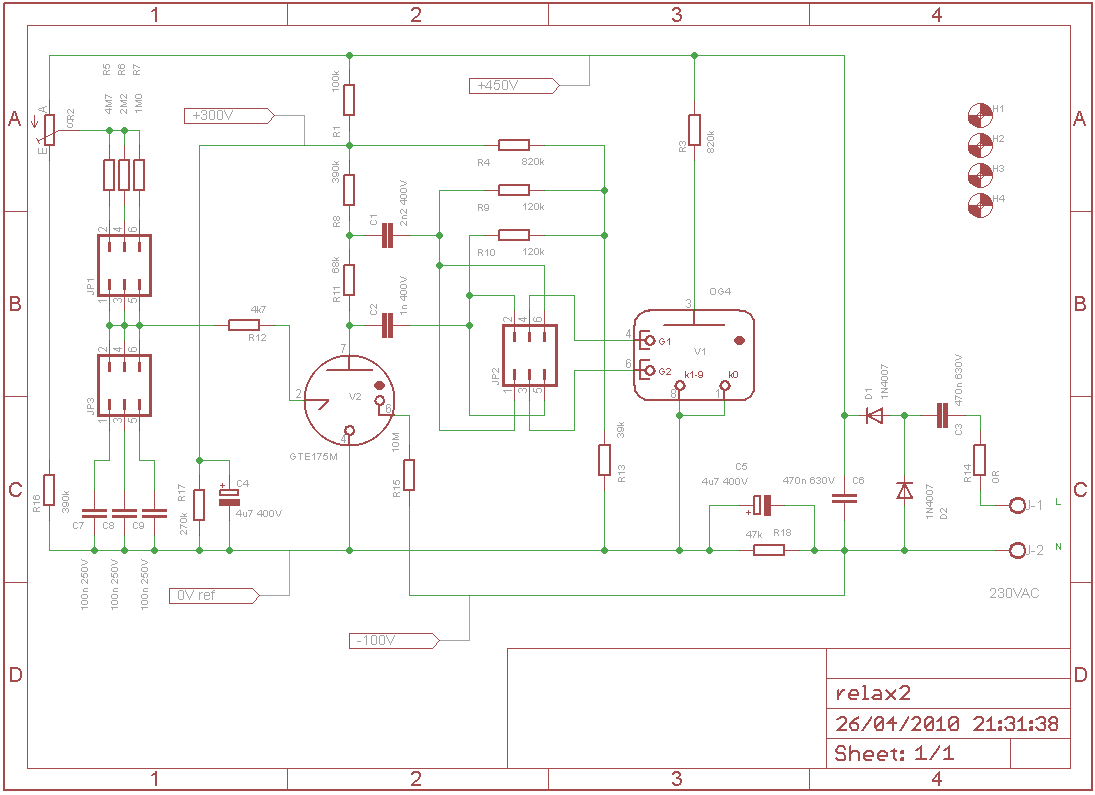
Mike Moorrees published an idea of using a neon relaxation oscillator as the timing element of a dekatron spinner. Dekatron spinners are commonly (although not always) mains driven so are pulsed at 50 or 60Hz. My extension used here was to use a GTE175M thyratron as both a dekatron driver and relaxation oscillator. This thyratron was designed as a dekatron stage coupler. So I have used the standard coupler stage on the output side but used the trigger electrode as a relaxation oscillator. I found the keep alive electrode was still needed.
The problem with this approach is that three voltages are required for operation:
- 475V for the dekatron anode
- 300V for the thyratron stage
- -100V for the keep alive electrode
My first breadboard version I ran from a bench PSU designed to deliver these voltages, for a more permanent solution I have used a mains voltage doubler (roughly 630V DC from 230V AC mains) and then arranged a voltage divider to produse the voltages required.
My small luxury item is I used two silicon diodes but then I have failed to produce an all valve spinner.
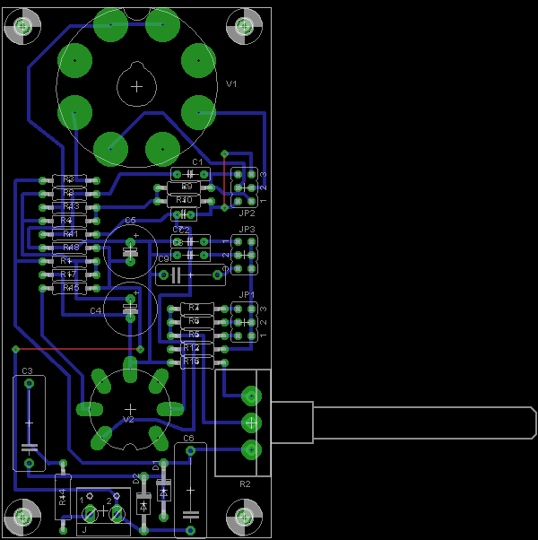
The board has a series of header pins for jumpers used to select the capacitor(s) and series resistor(s) used with the relaxtion oscillator. The oscillator can be run at speeds from seconds between steps to a blur. Another header sets the routing of the pulses to the guide electrodes so the direction of spin can be reversed.
Note that this circuit connects directly to the mains and has potentially fatal voltages present. The capacitors will retain a charge after the circuit has been disconnected from the mains. Please take care.
Schematic

PCB

You should look in the "/Dekatron Projects/All Toob Dekatron Spinner 1" folder.
