Simple Solar Water Heater Controller

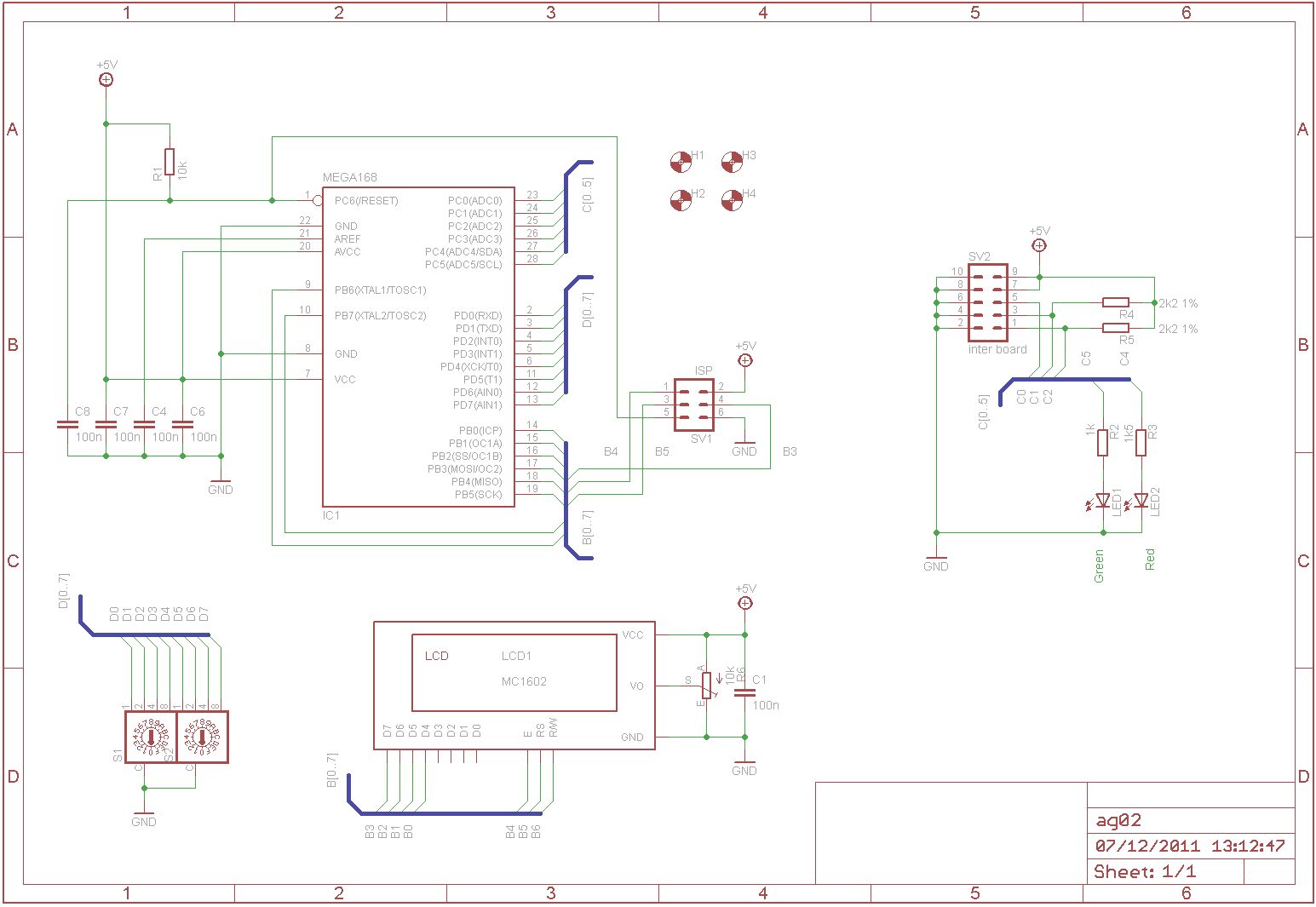
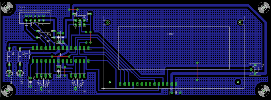
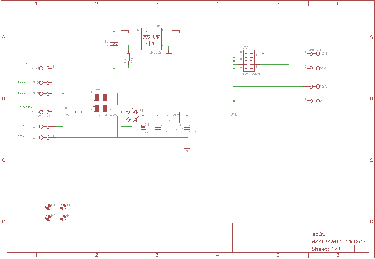
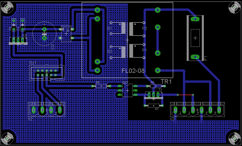
Schematic and PCB
The design features:
- Two boards "display" and "power"
- 10 way ribbon connector between the two boards
- Atmel mega168
- LCD display for temperature readings
- Red LED to show power is on and the mega is running
- Green LED to show pump status
- Two rotary switches to allow the pump on and off temperatures to be adjusted
- Opto isolated triac to switch the mains supply to the pump
- 5 V DC supply
Two of the mega ADC inputs are connected to two temperature sensors one on the pipework near the tank outlet (pump inlet) and one on the solar collector outlet. The temperature difference between these two sensors is used to determine if the pump should be run or not.
The sensors I used were from Rapid electronics (they have a resistance at 25°C of 10k and a B coefficient of 3435). If different sensors are to be used then it may be necessary to recompile the code.
You should look in the "/Home Projects/Solar Water Heater" folder - PCB layout only - no software.
Construction
The populated display board looks like this:

and the power board like this:

The two boards were built into a clear lid box (photo above) with separate cable glands for the mains, pump and sensor leads. The power board is mounted inside the bottom half of the box; the display board inside the clear lid. This construction allows the connections to the outside world to be fixed in place and allows the display panel and its micro controller to be removed. Additional holes are drilled in the clear lid to give access to the control switches and LCD contrast pot.
Software
Not available.
Operating
The LCD contrast control just needs setting to give a readable display and then left alone.
The two switch controls require a slightly longer explaination. The controller wants to switch on the circulating pump when there is a temperature difference between the tank temperature (measured on the pump inlet pipe) and the solar collector outlet temperature. This temperature difference needs to be a few °C to prevent the pump switching on and off frequently. Additionally, as the temperature difference falls there needs to be some hysteresis again to prevent the pump switching frequently. These temperatures are controlled by the two rotary switches.
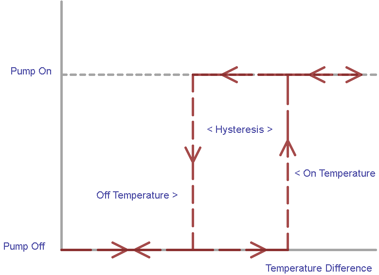
Starting with the pump off…
- The pump switches on when the temperature difference exceeds the "on temperature" (the "off temperature" plus the "hysteresis temperature")
- The pump then remains on as long as the temperature difference exceeds the "off temperature"
- The pump is switched off when the temperature difference falls below the "off temperature"
Each switch position increments increments its temperature setting by 0.5°C; giving each a range of 0 - 7.5°C and 0.5 - 14.5°C "on temperature" range (see below for the reason why 0 - 15°C is not realised). In practice I have found an "off" setting of 2°C and a hysteresis of 4°C works well for my system. But these temperature settings should be optimised for a particular installation.
The two rotary switches also allow the pump to be held off or forced to run:
- Setting both rotary switches to the 0 position will hold the pump off
- Setting both rotary switched to the F position will force the pump on
