Oscilloscope Clock
Introduction
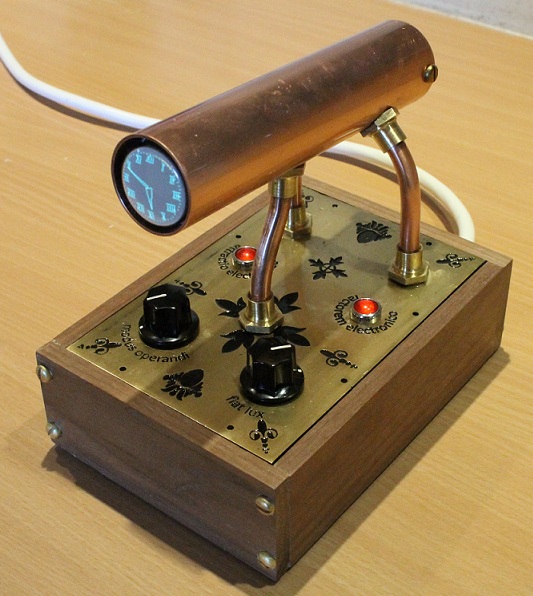
This is my first fully finished scope clock after a few false starts and a variety of experiments. It is a simple clock using only 5 ICs (one of those could easily be omitted and another is the 5V regulator) and 6 transistors. It uses a 25mm diameter scope tube in a "steampunk" style enclosure of copper, brass and walnut.
Scope Clock
There are plenty of designs of scope clocks on the internet - I'm not going to provide a list as google will do that for you better than I can. There are lots of pictures on google images as well. So I'm going to leap straight in and describe this clock. This is my first scope clock so I have used many elements from other projects that I knew would work well in this application. My basic design consists of:
- DH3/91 (CV2302, 1CP1) 25mm scope tube
- AD7302 DAC
- Blanking and deflection amplifiers from the OZ2CPU design
- Voltage multiplers from a 30V RMS input to give about +350V DC and -350V DC for the CRT
- LM2576-5 regulator for the 5V DC supply from 15V RMS input (without heat generation)
- ATMEGA328P microcontroller slightly overclocked at 22.1184 MHz
- DS1307 real time clock with battery backup
- Additional 64K EEPROM storage for text messages and four letter words
- MM232R module for a serial/USB connection
- Rotary encoder for the display mode selection
- 0-15V RMS 0-15V RMS 15VA toroidal transformer with an additional winding added to supply 6.3V RMS at 0.3A for the tube heater (a trick I use a lot when additional or auxillary windings are needed).
Such a dinky little tube:

I was aiming at a small overall size as the scope tube itself is so small and didn't want the final case to dominate the tube. Also, I was not trying to extend my ideas beyond a design that I was very confident would work well. Finally, I was aiming the design only at the DH3/91 scope tube with little or no flexibility for other, especially larger, tubes to be used. "KISS" was applied. More complex designs could follow later but I was keen to experiment with ideas in the software as you will see in the next section.
Preview
A quick review of just a few of from the miriad number of possible clock faces together with some of the test screens and other displays.
The software section and command section in the Annex hint at why so many clock faces are possible.
Schematic and Layout

The schematic has notes describing the remaining off-board components. A component parts list is available in the Annexes.

The final layout I used is a double sided board measuring 130mm x 90mm. The board is in two overall regions with the 5V regulator and all the digital stuff on one side and the high voltage PSU and the analogue deflection and blanking amplifiers on the other. I did have a layout where these two regions were on physically separate boards which would allow other clock case shapes to be used. But the design shown here is the final single board layout only. (The two board layout is provided in the Annexes.)

The schematics and PCB layouts were created using Eagle and are available for download above. As always I am willing
to make this PCB (at cost) for anyone wanting to attempt this clock.
Unfortunately I have lost my ability to make PCBs at home and so I cannot offer PCBs for this clock anymore.
The following table shows how the scope tube is wired to the PCB. I have not used the scope tube pin labels from the datasheet but stuck with more conventional labels.
| Tube Pin | Datasheet Description | Schematic Label |
| 1 | f | heater connection (not on schematic) |
| 2 | g2,g4,D1′ | A1,A3,Y1 |
| 3 | D1 | Y2 (collector Q3) |
| 4 | D2′ | X1 (collector Q1) |
| 5 | g1 | GRID (collector Q6) |
| 6 | D2 | X2 (collector Q2) |
| 7 | k,g3 | CATHODE (junction R27 & C20) |
| 8 | f | heater connection (not on schematic) |
Downloads
You should look in the "/CRT Projects/Scope Clock 1" folder.
Construction
My original thoughts on construction was a clear plastic case with the tube on a support above the PCB. Very much a standard form for scope clocks. A second thought was to fall back on my favorite appearance that of some sort of retro 1960's laboratory instrument. Alan Flowers (Cork, Ireland) suggested "Steampunk" to me. I suppose you could arge that it cannot be Steampunk as the Victorians did not have oscilloscope tubes, but I used the typical construction materials of copper, brass and wood (I used walnut); but I didn't use any leather. I leave you to decide if it is Steampunk or not.
I etched a pattern onto the brass top plate on the enclosure using the equipment I normally use for making PCBs. The etching technique (my first attempts) is described here.
Software
N.B. The ZIP file only contains the source code for the mega at the moment - just .C and H files - the libraries and the executable images will follow together with the code to initialise the external eeprom. This ZIP is for the curious only.
The software was written using C and ASM, and compiled using the CodeVisionAVR version 2 compiler. A zip file containing the required fuse settings and compiled hex files; download information above.
My intention is to make the full source code available when I have finished its documentation and tidying. Please contact me if you want it sooner. But beware C purists that my C is perhaps a bit idiosyncratic but I like it as it is.
Initial Test Software
The purpose of this software was to test the board (it tests all functions except the external eeprom).
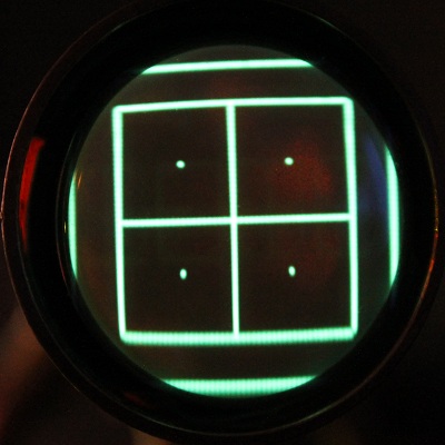
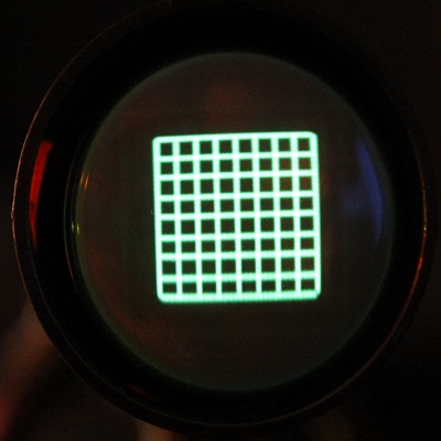
The test software displays the following screen:
The outer square is clipped by the circular tube face. The inner square is the limit that can be fully shown as it touches the tube edge. TRLB are the top, right, left and bottom and show that the tube is correctly wired and orientated (rotate the tube and/or swap the X1 and X2 connections as necessary). The display is moved in the X and Y directions each second. This is an anti-burn measure but in the final clock the movement is only once per hour. It helps to adjust the deflection amplifier position and size trimmers if the movement is initially more rapid.
The test software knows the following commands using the serial/USB connection (57600 buad, 8 bits, 1 stop bit, no parity):
- BUILD - report the software build and version
- DATE - report the current date
- DATE dd-mm-yyyy - set the date
- RESET - force the microcontroller to reset (may take upto 2 seconds)
- TIME - report the current time
- TIME hh:mm:ss - set the current time
- UTIL - report the microcontroller % utilisation
Finally, the rotary encoder can be tested by rotating it. A '+' is sent to the serial connection when the encoder is rotated clockwise and a '-' when it is rotated anticlockwise (swap the encoder connections if the sense is the reverse).
Final Software
The final operating software comes in three stages. The first two are programmed into the mega and run just once as they initialise the external eeprom. There may be a need to run either or both again if the content of the external eeprom requires revision. The third is the clock operating software.
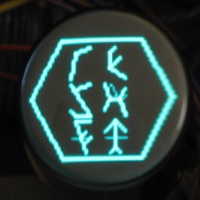
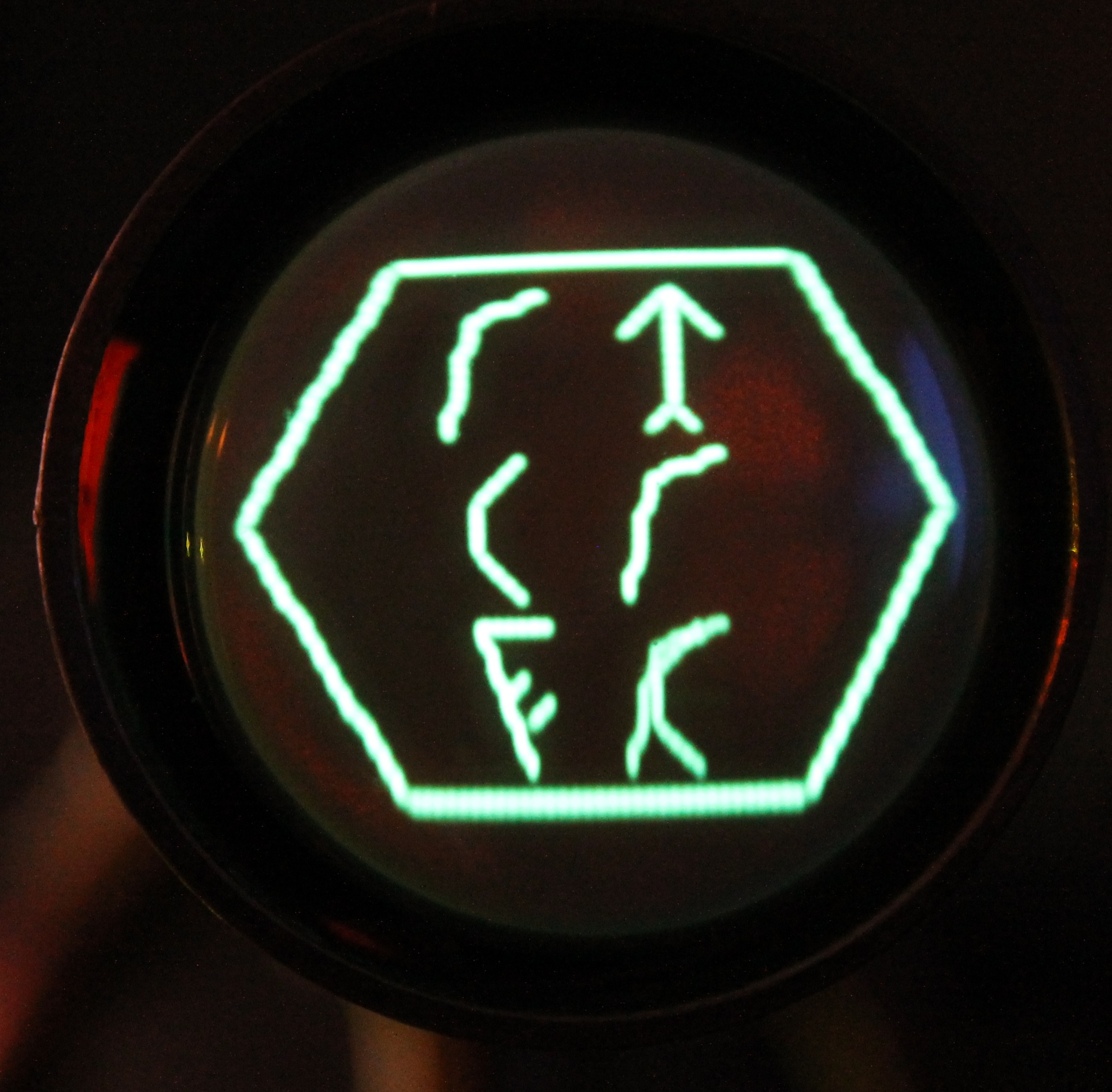
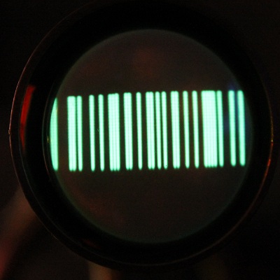
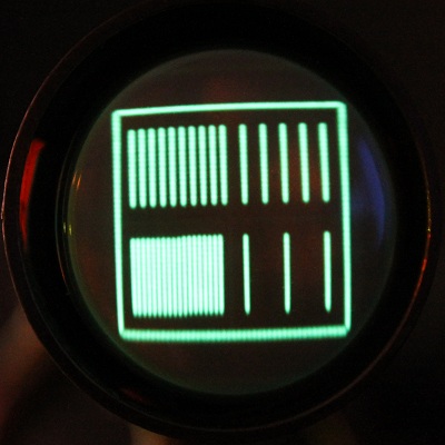
The clock can display in one of nineteen modes. The rotary encoder selects the active mode. Mode twenty is a sweep through a range of selected modes; the display pauses in each mode for an adjustable number of seconds. The twentyfirst mode is nor more than a blank tube. The displays available include analogue and digital clocks, some test screens, a four letter word generator and some clocks which are a bit more weird using a somewhat stylised Klingon font or a barcode (I have a friend who can read barcodes so it's here to challenge him, otherwise I don't find it very readable).
There are a number of common configuration options that apply across many of the clocks and tests:
- Display in Standard Time only or automatically switch between Standard Time and Daylight Saving Time using European or USA federal DST rules
- Supress leadings zeros where appropriate so, for example, display 07:30 as 7:30
- Display as a 12 hour or 24 hour clock
- Show or hide seconds
- Show or hide an AM-PM indicator
- Show or hide the display (in which case the sweep mode jumps over the mode without displaying it)
Analogue clocks
Of the nineteen modes, four are analogue clock faces. The clock faces can each be customised by changing:
- Hour hand shape and size
- Minute hand shape and size
- Second hand, choosing to display the hand, and if so its size
- Millisecond hand, choosing to display the hand, and if so its size
- The dial numbers, as not shown, 3, 6, 9, 12 or 1, 2, 3 …, radial position and font (Arabic, Roman, Klingon)
- Dial tick marks, as not shown, at 1 minute or 5 minute positions, as just dots or as ticks or a mixture of both, radial position and tick size
By the way of examples, the four default analogue faces are:
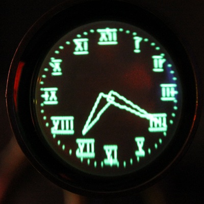
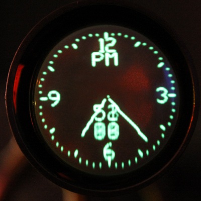
But don't be fooled here, there are not just these four, they can all be widely configured.
Digital, including Binary, Clocks
There are four digital (or alphanumerical if you prefer) and two clocks that just use '0' and '1' to display the time. Looking at these first:
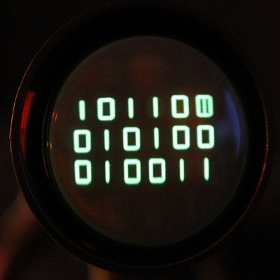
This is the time in binary. The top row is seconds (44, although the seconds was changing to 45 as I took the photo), the middle row is minutes (20) and the bottom row hours (19) i.e. 19:20:45.
The second binary clock is Binary Coded Decimal:
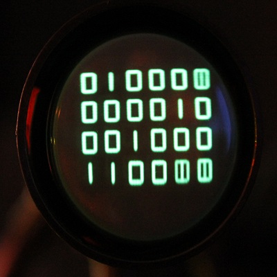
The leftmost column is 10's of hours (1) and the next is units of hours (9) giving the hour as 19. The middle pair of columns are minutes (2 and 0, giving 20. The rightmost columns give the seconds (just changing from 09 to 10). So the time is about 19:20:09 to 19:20:10.
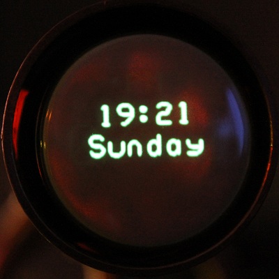
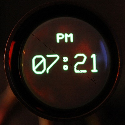
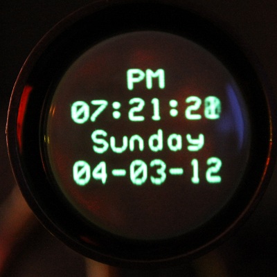
Digital clocks are just alpha numerical displays. The clock will show the time, the day of week and the date. A larger
font time can be used.
Three of the default digital clocks are (the fourth is a simplification):
Miscellaeous Clock
Four Letter Words
A range of four letter words including several rude words. There configuration options allow the rude words to be censored and the time period between the words changing to be altered.


Test Screens
Acknowledgments
OZ2CPU for inspiration, the deflection and blanking circuits
Alan Flowers for ideas and building a scope clock
Dave Povey for the ping-pong clock suggestion
John Rehwinkel for the AScope clock suggestion and the alternatives for the mains transformer used
Martin Forsberg for more, and more, and more... ideas
Annexes
Final Software Command Menu
The menu system uses a simple text entry method. The clock uses a USB serial port connecting using 57600 baud, 8 data bits 1 stop bit and no parity. A command is typed in, backspace can be used to remove characters typed in error, and Enter is pressed to process the command. The Esc key can be used to abandon the whole entry before Enter is pressed.
Command can be typed in full or abbreviated (lowercase letters are automatically converted to uppercase). So for example to hide analogue clock 3 you enter:
ANALOGUE 3 SHOW OFF
Or, fully abbreviated this becomes: A 3 SH 0
The abbreviated version is most useful when experimenting with a command to quickly see how the clock faces changes or the clock operation is changed etc.
Most commands take a parameter or several parameters; if the parameter or parameters are omitted then the current value is reported. So for example the SET DATE command will report the current date if no date parameter is provided. (The exception to this rule is the SYSTEM SEED command that sets the seed value used by the random number generator. If the parameter is omitted then a seed is generated using the current date and time from the real time clock.)
Finally, commands can be followed by a ? as a single parameter. The clock will reply with a brief help message and the options available for any required parameters. So for example BCD SHOW ? will provide brief description of the SHOW command and the options avaliable for the parameter it takes.
In this table | shows alternatives, for example 1|2|3|4 means enter a 1, 2, 3 or a 4.
…[…] is used to indicate the minimum length abreviated string i.e. without ambiguity. For example
D[IGITAL] shows that the DIGITAL command can be shortened to just D but SH[OW] indicates that the SHOW
subcommand can only be shortened to SH.
| Command | Selector | Subcmd | Parameters | Explaination |
|
A clock in an analogue fashion to display the time. Extensive control over clock hands, dial ticks and numbering. There are four analogue clocks to save; each can be configured completely differently. |
||||
| AN[ALOGUE] | 1|2|3|4 | A[MPM] | 0|OFF|1|ON | AMPM makes an AM/PM indicator visible. It takes a single parameter which may be 0 or OFF for to hide the indicator only OR 1 or ON to show it. |
| C[ENTRE] | 0|OFF|1|ON | CENTRE makes a clock centred dot visible. It takes a single parameter which may be 0 or OFF for to hide the dot only OR 1 or ON to show the dot. | ||
| D[ST] | 0|1|2 |
DST controls the automatic change over to daylight saving time. It takes a single parameter:
|
||
| H[OUR] | MODE, STEP, OUTER, INNER, WIDTH |
HOUR controls the hour hand. It takes 5 comma separated parameters. MODE is a value from 1 to 4:
|
||
| MA[RK] | MODE, OUTER, INNER |
MARK controls the dial edge dashes and dots. It takes 3 comma separated parameters. MODE is a value from 1 to 5:
|
||
| MIL[LI] | MODE, OUTER, INNER |
MILLI controls the millisecond hand. It takes 3 comma separated parameters. MODE is a value from 1 to 5:
|
||
| MIN[UTE] | MODE, OUTER, INNER, WIDTH |
MINUTE controls the minute hand. It takes 4 comma separated parameters. MODE is a value from 1 to 4:
|
||
| N[UMBER] | MODE, RADIUS |
NUMBER controls the dial hour numbering. It takes 2 comma separated paramaters. MODE is a value from 1 to 7:
|
||
| SE[COND] | MODE, OUTER, INNER |
MILLI controls the second hand. It takes 3 comma separated parameters. MODE is a value from 1 to 5:
|
||
| SH[OW] | 0|OFF|1|ON | Makes the analogue clock available when the display mode is sweep | ||
|
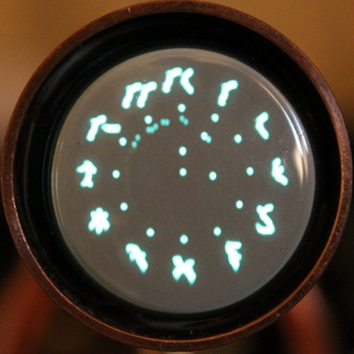
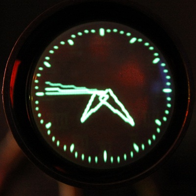
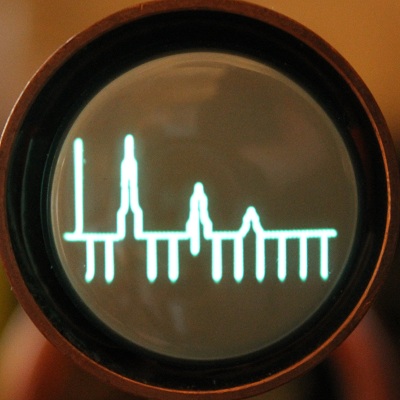
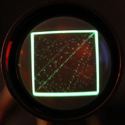
Use A-Scope radar to show hours, minutes and seconds. The time is shown on the horizontal scale of downward ticks (hourly, 5 minute, 5 second separation). The reflected radar pulses mark the hours (tallest, but adjustable, in this example), minutes and seconds. The reflected pulse move from right to left as the "detected" objects get closer. |
||||
| AS[COPE] | D[ST] | 0|1|2 |
DST controls the automatic change over to daylight saving time. It takes a single parameter:
|
|
| P[EAKS] | HOUR, MINUTE, SECOND, TICK, TX | PEAKS sets the height of the radar pulses or signal reflections. The 5 comma separated parameters are the height of the hour reflection, minute reflection, second reflection, distance timing ticks (downwards) and the radar "transmitted" pulse. | ||
| SE[CS] | 0|OFF|1|ON |
SECS controls whether the second peak is shown or hidden. It takes a single parameter which may be 0 or OFF to hide the peak OR 1 or ON to show it. |
||
| SH[OW] | 0|OFF|1|ON | Makes the A-Scope clock available when the display mode is sweep | ||
|
Use bar code 39 to show hours and minutes. |
||||
| BA[RCODE] | D[ST] | 0|1|2 |
DST controls the automatic change over to daylight saving time. It takes a single parameter:
|
|
| H[OUR] | 0|OFF|1|ON |
HOUR controls the clock hour range: a 12 hour or 24 hour display. It takes a single parameter which may be 0 or OFF for 24 hour display OR 1 or ON for a 12 hour display. |
||
| S[HOW] | 0|OFF|1|ON | Makes the barcode clock available when the display mode is sweep | ||
|
Use binary coded decimal (BCD) to show the time. The display consists of 6 columns, 4 if seconds are not shown, the leftmost pair of columns are hours, middle are minutes and rightmost are seconds. In each pair the left column is 10's the right column the units. |
||||
| BC[D] | D[ST] | 0|1|2 |
DST controls the automatic change over to daylight saving time. It takes a single parameter:
|
|
| H[OUR] | 0|OFF|1|ON |
HOUR controls the clock hour range: a 12 hour or 24 hour display. It takes a single parameter which may be 0 or OFF for 24 hour display OR 1 or ON for a 12 hour display. |
||
| L[EAD] | 0|OFF|1|ON |
LEAD controls whether leading zeros are shown or hidden. It takes a single parameter which may be 0 or OFF to hide leading 0s OR 1 or ON to show them. |
||
| SE[CS] | 0|OFF|1|ON |
SECS controls whether the second columns are shown or hidden. It takes a single parameter which may be 0 or OFF to hide seconds OR 1 or ON to show them. |
||
| SH[OW] | 0|OFF|1|ON | Makes the BCD clock available when the display mode is sweep | ||
|
Use binary to show the time. The display consists of 3 rows, 2 if seconds are not shown, the top row is seconds, the middle row shows minutes and the bottom row shows hours. |
||||
| BI[NARY] | D[ST] | 0|1|2 |
DST controls the automatic change over to daylight saving time. It takes a single parameter:
|
|
| H[OUR] | 0|OFF|1|ON |
HOUR controls the clock hour range: a 12 hour or 24 hour display. It takes a single parameter which may be 0 or OFF for 24 hour display OR 1 or ON for a 12 hour display. |
||
| L[EAD] | 0|OFF|1|ON |
LEAD controls whether leading zeros are shown or hidden. It takes a single parameter which may be 0 or OFF to hide leading 0s OR 1 or ON to show them. |
||
| SE[CS] | 0|OFF|1|ON |
SECS controls whether the second columns are shown or hidden. It takes a single parameter which may be 0 or OFF to hide seconds 0s OR 1 or ON to show them. |
||
| SH[OW] | 0|OFF|1|ON | Makes the binary clock available when the display mode is sweep | ||
|
Bouncing balls test/demonstration - just a bit of fun. |
||||
| BO[UNCE] | B[ALLS] | number | Sets the number "in-play". The command takes a single parameter which must lie between 1 and 20. | |
| R[ESTART] | RESTART fires the balls again. It takes no parameters. Restart is called automatically each minute. | |||
| S[HOW] | 0|OFF|1|ON | Makes the bounce test available when the display mode is sweep | ||
|
A clock in a digital fashion display the time and optionally the day of the week, the date and an AM-PM indicator. There are four digital clocks to save; each can be configured completely differently. |
||||
| D[IGITAL] | 1|2|3|4 | A[MPM] | 0|OFF|1|ON |
AMPM makes an AM/PM indicator visible. It takes a single parameter which may be 0 or OFF for to hide the indicator only OR 1 or ON to show it. |
| B[IG] | 0|OFF|1|ON |
BIG make the font bigger but suppresses some other display options. It takes a single parameter which may be 0 or OFF for a standard font only OR 1 or ON for the big font. |
||
| DA[TE] | 0|OFF|1|ON |
DATE makes the date visible. It takes a single parameter which may be 0 or OFF to hide the date OR 1 or ON to show the date. |
||
| DO[W] | 0|OFF|1|ON |
DOW makes the day of the week visible. It takes a single parameter which may be 0 or OFF to hide the DOW OR 1 or ON to show the DOW. |
||
| DS[T] | 0|1|2 |
DST controls the automatic change over to daylight saving time. It takes a single parameter:
|
||
| H[OUR] | 0|OFF|1|ON |
HOUR controls the clock hour range: a 12 hour or 24 hour display. It takes a single parameter which may be 0 or OFF for 24 hour display OR 1 or ON for a 12 hour display. |
||
| L[EAD] | 0|OFF|1|ON |
LEAD controls whether leading zeros are shown or hidden. It takes a single parameter which may be 0 or OFF to hide leading 0s OR 1 or ON to show them. |
||
| SE[CS] | 0|OFF|1|ON |
SECS controls whether the second columns are shown or hidden. It takes a single parameter which may be 0 or OFF to hide seconds 0s OR 1 or ON to show them. |
||
| SH[OW] | 0|OFF|1|ON | Makes the digital clock available when the display mode is sweep | ||
|
Display extents test for deflection amplifer set up. |
||||
| E[XTENT] | S[HOW] | 0|OFF|1|ON | Makes the extent test available when the display mode is sweep | |
|
Random Four Letter Words |
||||
| F[LW] | C[HANGE] | number | Sets the time in seconds that each FLW is shown for. The command takes a single parameter which must lie between 1 and 20. | |
| R[UDE] | 0|OFF|1|ON |
RUDE controls whether certain "robust" English words are shown or hidden. It takes a single parameter which may be 0 or OFF to hide OR 1 or ON to show them. By default RUDE is OFF. |
||
| S[HOW] | 0|OFF|1|ON | Makes the FLW display available when the display mode is sweep | ||
|
Graticule display for focus, display resolution and linearity tests. |
||||
| G[RATICULE] | D[ENSITY] | 1|2|3|4|5 | Sets the density of the graticule lines. The command takes a single parameter which must lie between 1 and 5. | |
| S[HOW] | 0|OFF|1|ON | Makes the graticule test available when the display mode is sweep | ||
|
Use Klingon numbers to show the time. The display consists of 3 rows, 2 if seconds are not shown, the top row is hours, the middle row shows minutes and the bottom row shows seconds. |
||||
| K[LINGON] | D[ST] | 0|1|2 |
DST controls the automatic change over to daylight saving time. It takes a single parameter:
|
|
| H[OUR] | 0|OFF|1|ON |
HOUR controls the clock hour range: a 12 hour or 24 hour display. It takes a single parameter which may be 0 or OFF for 24 hour display OR 1 or ON for a 12 hour display. |
||
| L[EAD] | 0|OFF|1|ON |
LEAD controls whether leading zeros are shown or hidden. It takes a single parameter which may be 0 or OFF to hide leading 0s OR 1 or ON to show them. |
||
| SE[CS] | 0|OFF|1|ON |
SECS controls whether the second columns are shown or hidden. It takes a single parameter which may be 0 or OFF to hide seconds 0s OR 1 or ON to show them. |
||
| SH[OW] | 0|OFF|1|ON | Makes the Klingon clock available when the display mode is sweep | ||
| Change display mode (instead of moving the rotary encoder). | ||||
| M[ODE] | number |
MODE accepts the following number codes:
|
||
|
Parallel lines display for focus, display resolution and linearity tests. |
||||
| PA[RALLEL] | S[HOW] | 0|OFF|1|ON | Makes the parallel line test available when the display mode is sweep | |
|
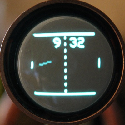
A game of ping-pong (table tennis if you wish) played for ever with the "score" showing the time in hours and minutes. |
||||
| PI[NPONG] | D[ST] | 0|1|2 |
DST controls the automatic change over to daylight saving time. It takes a single parameter:
|
|
| H[OUR] | 0|OFF|1|ON |
HOUR controls the clock hour range: a 12 hour or 24 hour display. It takes a single parameter which may be 0 or OFF for 24 hour display OR 1 or ON for a 12 hour display. |
||
| L[EAD] | 0|OFF|1|ON |
LEAD controls whether leading zeros are shown or hidden. It takes a single parameter which may be 0 or OFF to hide leading 0s OR 1 or ON to show them. |
||
| SH[OW] | 0|OFF|1|ON | Makes the pingpong clock available when the display mode is sweep | ||
| The SET menu contains command to adjust the date and time used by the real time clock. This information is held separately to the configuration information and will not change as a result of the SYSTEM DEFAULT command. The SET data is held in the memory sustained by the on-board battery so the information will be lost if the battery is removed or goes flat. | ||||
| SE[T] | A[DJUST] | number | This value is used to adjust the time once per week (midnight Sunday) so the clock keeps better time. The value may be positive or negative. The value can be determined by running the clock for several months and noting the gain or loss in seconds and calculating the gain or loss per week. | |
| D[ATE] |
|
Enter the date in the format specified by the SET FORMAT command. The UTC date should be used. |
||
| F[ORMAT] | number |
Change the format used to display the date.
The options are:
|
||
| T[IME] | hh:mm:ss | Enter the time in the required format. The UTC time should be used. | ||
| Z[ONE] | number | Enter the local time zone as a displacement from UTC. The number must lie between -12 and +12 inclusive. | ||
| System menu contains a bunch of miscellaneous commands. | ||||
| SY[STEM] | B[UILD] | Report firmware version and build information. | ||
| D[EFAULT] | DEFAULT restores the "factory default" configuration settings. This command does not change the date and time settings. | |||
| J[IGGLE] | number | The clock has a simple anti-burn measure where the image is moved left and right, up and down by one pixel once per hour. There are 4 positions in total. Enter a number between 0 and 3 to move to the corresponding position. | ||
| R[ESET] | Force the microcontroller to reset. The command takes upto 2 seconds to operate. | |||
| SE[ED] | number | Enter a new seed value for the random number generator to use. The main effect will be that the order of the four letter words becomes repeatable. If no parameter is provided then a seed number is generated using the date and time. | ||
| SW[EEP] | number | Enter the time in seconds between the display changing in sweep mode. | ||
| U[TIL] | Reports the approximate time taken by the microcontroller to service certain tasks: the calculations it performs once every 20mS, the additional calculations carried out every second, and the time taken to draw the image on the tube. The remaining time is used for other functions (servicing the clock chip, the serial port, the menus etc). Obviously, the utilisation must not exceed 100%. If the display starts to flicker then check the utilisation - if too many options (especially on the analogue clock) are turned on then the microcontoller may not have enough time to service all the demands (the analogue display will look very congested with too many options on which is likely to be undesirable as well). | |||
Parts List
None of these components should be difficult to source. At the time of writing this webpage the tube and its socket are readily available from tube suppliers and Ebay. A number of the components (especially the electrolytic capacitors) are size critical, so be sure to buy the correct diameter components if the parts are not sourced from Farnell or Rapid.
| Part | Description | Farnell Code | Rapid Code | Dimensions |
| TR1 | 15VA 2X 15V toroidal transformer | 1675046 | Note this transformer has a single 230V primary - see note 1 | |
| R1 - R4, R25 | 220k 5% 0.25W | |||
| R5-7, R14, R19, R21, R24 | 1M 5% 0.25W | |||
| R8, R10 | 2k2 5% 0.25W | |||
| R9, R11, R12, R13 | 10k 25turn trimmer | 9353704 | See note 3 | |
| R15-R18 | 4k7 5% 0.25W | |||
| R20, R22, R23, R30, R33 | 10k 5% 0.25W | |||
| R26 | 100k 5% 0.25W | |||
| R27 | 500k 25turn trimmer | 9353828 | See note 3 | |
| R28 | 100k potentiometer | 1684818 | ||
| R26 | 33k 5% 0.25W | |||
| R31, R32 | 3k3 5% 0.25W | |||
| IC1 | LM2576-5 | 1564682 | 82-0664 | |
| IC2 | DS1307 | 1188042 | 82-0567 | |
| IC3 | AT24C512 | 1908134 | ||
| IC4 | AD7302BNZ | 1079330 | ||
| IC5 | ATMEGA328P | 1715487 | ||
| D1-D11, D13, D15-D18 | 1N4004 | 47-3136 | ||
| D12 | 1N4001 | 47-3130 | ||
| D14 | 1N5820 | 47-2546 | ||
| L1 | 220uH subminature axial | 88-1037 | 7.2 mm lead spacing 13 mm diameter | |
| Q1-4, Q6 | ZTX458 | 9526668 | ||
| Q5 | ZTX558 | 9526676 | ||
| Q7 | 32.768 kHz crystal | 90-3052 | ||
| Q8 | 22.1184 MHz crystal | 90-3062 | ||
| B1 | CR2032 Cell CR2032 Holder |
18-0490 18-0498 |
flat 24mm diameter two pin - 20 mm spaced |
|
| C1-C13, C17-C19 | 100u 100V electrolytic | 9693947 | 5 mm lead spacing 10 mm can diameter |
|
| C14 | 10n ceramic | 08-0232 | 2.5mm leg spacing | |
| C15 | 2200u 35V electolytic | 11-0760 | 5 mm lead spacing 13 mm can diameter |
|
| C16 | 1000u 10v electolytic | 11-0760 | 5 mm lead spacing 10 mm can diameter |
|
| C20 | 10u 100V electrolytic | 1236690 | 3.5 mm lead spacing 8 mm can diameter |
|
| C21-C25 | 100n polyester | 10-3260 | 5mm lead spacing | |
| C26, C27 | 22p ceramic | 08-0046 | 2.5 mm lead spacing | |
| X (USB module) | FTDI MM232R | 1146037 | ||
| Rotary encoder | Alps | 1607976 | ECW1J-B24-BC0024L - see note 2 | |
| J (ISP connection) | 2 x 3 header | |||
| V1 | DH3/91 | from Ebay | ||
| V1 base | Loctal base | from Ebay | ||
| 2 off | DIL8 socket | 22-0150 | ||
| 1 off | DIL28-3 socket | 22-0175 | ||
| 1 off | DIL20 socket | 22-0170 | ||
Note 1: The transformer I used has a single 230V primary. Alternatives include Farnell 3068572 or Newark 38K4871 (Multicomp MCTA015/15 or Toroid International TA015/15). This is a dual primary transformer suitable for 115V or 230V mains at 50 or 60Hz.
Note 2: This rotary encoder used to be supplied with a lock nut for panel mounting but no longer is. The thread is some sort of fine M9 (and I do mean M9). I'm looking for an alternative but the clock has only been tested with this encoder so far.
Note 3: Set the trimmer pots to mid travel using an ohmmeter before fitting.
Alternative PCB Layout
The Eagle zip file also contains a pcb layout for two boards. The 5V supply and digital components on one card and the HV supply and deflection/blanking amplifiers on a second. The two cards are designed to allow them to be stacked. These cards allow other shapes of cases to be considered.

The long red hatch tracks (layer 15 in Eagle) show how the two boards are connected and are not physical tracks on the PCB.
This layout has been built and tested.