+2.1kV Power supply for Scope Clock Due
Introduction
As the frequency of operation of a CRT is increased, especially where fast transients are to be seen or photographed, the trace has to be brighter. This can be accomplished by increasing the beam current so that more electrons reach the phosphor. However, increasing the beam current means a larger spot size, therefore the beam current must be limited in value. The only other way of obtaining more brightness is to increase the velocity of each electron by raising the accelerating voltage. However, the deflection sensitivity is inversely proportional to the accelerating voltage applied before the deflecting plates. This is a serious disadvantage, as it is difficult to get a large deflecting voltage at high frequencies, particularly when transistors are used. The actual sensitivity will depend on the deflecting plate size and spacing; an older mono-accelerator tube with a final anode voltage of 4 kV may have a deflection factor of 50 volts/cm. Thus, to get a 3 cm peak deflection (i.e. a total of 6 cm peak-to-peak) requires a deflecting voltage of 3 x 50 = 150 volts peak (or 300 V p-p). If the accelerating voltage becomes 8 kV then the required deflecting voltage is 300 volts peak or 600 V p-p).
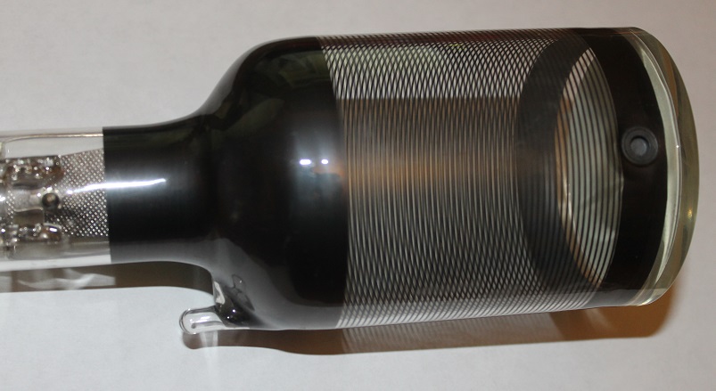
To overcome this limitation, post deflection acceleration (PDA) is used. The general idea is that if the final anode of the gun is given a voltage of, say, only 1 to 2 kV, the electron beam will have a relatively low velocity when passing through the deflecting plates, and the deflection sensitivity will be high. If the electrons are accelerated after deflection it will have little or no effect on the deflection sensitivity. There are several methods of doing this. One is to use a high resistance helix (e.g. 500 MΩ) deposited on the inside of the tube. The screen end of this helix is connected to a high voltage, and the other end to a potential at or near that of the final anode. The PDA acceleration voltage required was commonly 4 to 10 kV, but may go as high as 20 kV.

Soviet 8ЛО3И CRT has a spiral PDA
From the point of view of a scope clock builder, viewing fast transients and photography are not our goals. However there are many fine CRTs available that have PDA. If incorrect voltages are applied to such a CRT it can result in a dim trace, distortions, poor focus or variable focus over the CRT face. PDA cannot therefore be ignored.
The PDA power supply here is a simple multiplier strip run from the Scope Clock Due's flyback power supply. It will generate upto about +2.1kV with respect to ground. Since the cathode potential in Scope Clock Due can be as low as -1.9kV, this multiplier is suitable for CRTs requiring up to about 4kV PDA voltage relative to the cathode.
Quick Links
Documentation
Documentation - photos, Eagle files, manuals, blurb, lots o' stuff in general are available on a dropbox.
Quick LinksKit Availability and Prices
The electronics kit is available in two forms:
Minimal Electronics Kit

This is the bare PCB only. You will have to buy all the remaining components. I bought them from Farnell (Element14), Digikey, Mouser etc. If you are going down this route then I assume you know what you are doing…
The price of this is here.
Complete Kit

This is the kit when assembled with all the SMD parts fitted or you can have the fun of soldering the birdseed yourself.
The price of this is here.
PDA Connector

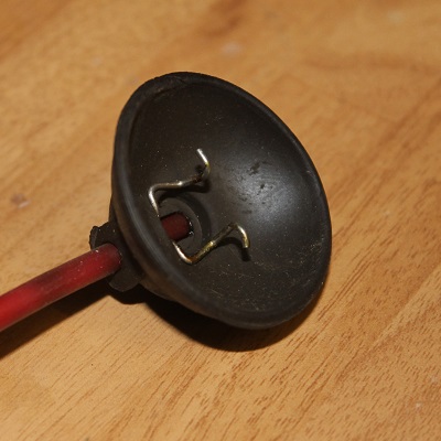
I have number of NOS PDA connectors available (the common type).
The price of this is here.
Shipping
Shipping details are here.
Quick LinksContact
Please contact me with any questions!