Introduction
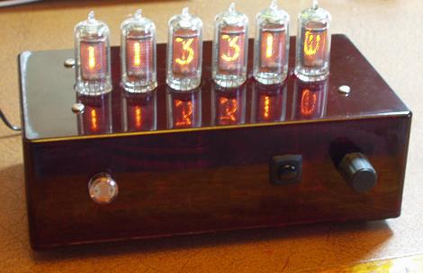
Having seen a nixie clock in our kitchen, a friend asked me to build him a nixie clock ("retro with the six tubes sticking out of the top of a box"). We agreed on XN11 nixies (from EBay) with manual time set. I added other feature such as PWM brightness control, date, automatic GMT/BST selection and battery back up so the date and time would not be lost during a power outage.
Design outline
The box measures 191 x 110 x 61 mm and is made of translucent red polycarbonate.

I used a switched mode power supply for both the 5 volt digital supply and the 180 volt anode supply for the nixies and an ATMEGA32 microcontroller to provide the "intellegence" required to control the clock (overkill but I had one in my junk box). I used a PCF8583 clock chip with a battery back up which convienently uses a TWI (I2C) bus for connection to the microcontroller, provides a one-second interrupt and contains both time and date functions. The chip also contains 240 bytes of free battery backed memory. The nixie display driver is a Supertex HV5522 which has 32 high voltage open drain outputs. To drive 6 nixie tubes this suggested a multiplex arrangement of 2 groups of 3 tubes - 30 outputs to the nixie cathodes and 2 remaining to drive the anodes (via each via a pnp transistor).
Microcontroller, clock and PSU card
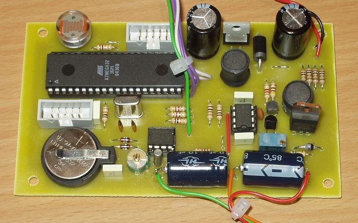
This card carries the switch mode power supplies for 5V and 180V for the nixies, the microcontroller and clock. The LDR will eventually be located on the outside of the box where it will sense ambient light level and the nixie's brightness will be controlled using PWM.
One 10 pin header is for the programmer and the other is connected by a ribbon cable to the display board where it provides signals and power to the HV5522 driver.
Off board as well are a single push button and a rotary encoder to set the date, time, clock mode etc. by mean of a simple menu system.
All straight forward with just repetition of previously tried sub-circuits.
Driver and Display Card
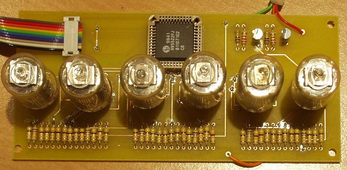
This card carries the 6 XN11 nixies and the HV5522 driver chip. The anode drivers are MPSA92 pnp transistors driven from two outputs on the HV5522.
The anodes and cathodes all have "centre-pull" resistors to help eliminate ghosting in the display.
Schematics and PCBs
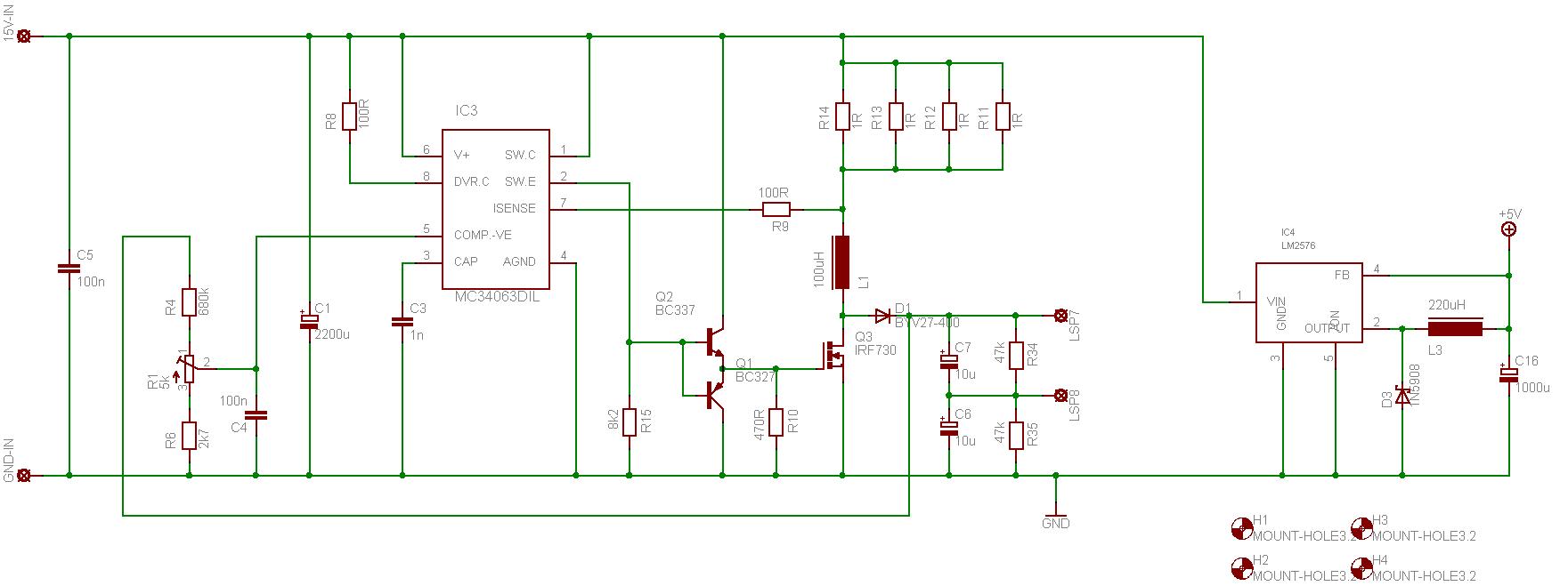
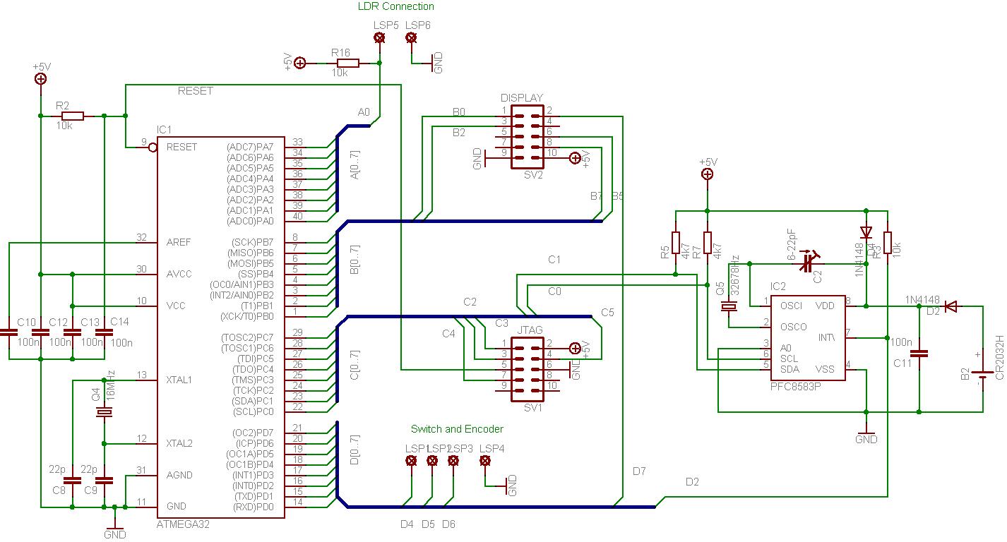

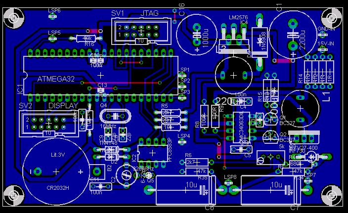
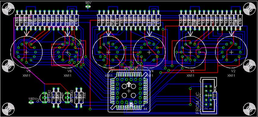
This is a home-made double-sided PCB with the vias connected using some tiny copper rivets (0.6mm od, 0.4mm id). I don't use the special punch machine but fit them with tweezers and then just solder them in place. You get a much neater and quicker finish than using wire links.
You should look in the "/Nixie Projects/Nixie Clock in a Red Box" folder.
Software
The software is currently awaiting a full re-write and is not available. Sorry. (This ain't going to happen now.)
Menus
Although the software is unavailable I'll document the menu system here for interest and future adaptation.
| Menu | Range of values | Default | Function | Comments |
| 70 | 2000 - 2100 | 2000 | Set Year | The date (menu 70, 71, 72) must be set correctly for the automatic BST/GMT display to operate correctly |
| 71 | 1 - 12 | 1 | Set Month | |
| 72 | 1 - 31 | 1 | Set Day | Actual day range depends on year and month setting |
| 73 | 0 - 23 | 0 | Set Hour | Time is always set to GMT irrespective of whether it is GMT or BST. The clock determines GMT/BST and displays the correct time |
| 74 | 0 - 59 | 0 | Set Minute | |
| 75 | 0 - 59 | 0 | Set Second | Time is hhmmss display |
| 80 | 0 - 1 | 0 | 12 or 24 hour display | 0 = 12 hour display; 1 = 24 hour display (default); e.g. 17:15 or 05:15 displayed. |
| 81 | 0 - 1 | 1 | Leading hour zero display | 0 = leading hour zero not displayed; 1 = leading hour zero displayed; e.g.5:15 or 05:15 displayed. |
| 82 | 0 - 255 | 0 | Display Brightness | 0 = automatic; 1 = dimmest (minimum value about 15, display will go blank when selecting 1) 255 = brightest. |
| 83 | 0 - 6 | 0 | Date display per minute | 0 = never; 1 = once, i.e. every 60 seconds; 2 = every 30 seconds; 3 = every 20 seconds; 4 = every 15; seconds; 5 = every 12 seconds; 6 = every 10 seconds. |
| 84 | 0 - 9 | 5 | Date Display Time | In seconds; e.g. menu 83 = 3, menu 84 = 5 will show time for 15 seconds and date for 5 seconds repeatedly. Date is displayed as ddmmyy. |
| 85 | 0 - 1 | 0 | Adjust Sign | 0 = subtract; 1 = add. |
| 86 | 0 - 29 | 0 | Seconds Adjust | Menus 85 and 86 enable a value between -29 and + 29 seconds to be added to the clock per day (added just after midnight) e.g. menu 85 = 0 and menu 86 = 5 will deduct 5 seconds per day from the clock; e.g. menu 85 = 1 and menu 86 = 2 will add 2 seconds per day to the clock. |
| 99 | - | - | System Reset | Count down for 30 seconds then cause system to reset to midnight on 1/1/2000 and the default values set for all menu items. Step over menu 99 within the countdown to put the clock back into clock mode. |
