
Introduction
Building and testing valve equipment requires a high voltage power supply and low voltage for the valve heaters. I have built a few power supplies, mainly for use with dekatrons and nixies and there associated coupling stages. I saw a Heathkit Model IP-17 Regulated High Voltage Power Supply on Ebay. The seller was in the UK so postage would not be outrageous; when I one the unit and received it in the post I set about some alterations, pre-emptive component replacement and testing. These are my notes.
Heathkit Blurb
The power supply is described by Heathkit as being "…is a compact, convenient source of variable high voltage, variable bias voltage, and filament [aka heater] voltage for laboratories and workshops. Separate panel meters are provided for accurate monitoring of the DC output current and voltage. All output binding posts are insulated from the chassis to allow the high (B+) and bias (C-) voltages to be used as either negative or positive voltage sources.

The high voltage output provides 0 to 400 volts or reguated DC at currents upto 100mA; the bias output provides negative voltage fro 0 to -100 volts DC upto 1mA; and the heater outputs provide 6.3VAC at 4A or 12.6VAC at 2A.
Schematic

Manual PDF
You should look in the "/Workshop Projects/Heathkit IP17 Restoration" folder.
Alterations & New Components
The Ebay seller described the unit as being … an old Heathkit unit and for it's age it is in very nice condition. …Physically and cosmetically it is attractive and sound and that the unit was wired for 115V mains operation. The seller's description was not inaccurate and I was very pleased with the unit when I unpacked it.
My plan of attack was (the page numbers reference the Heathkit manual):
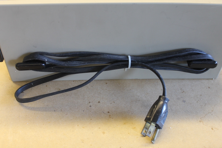
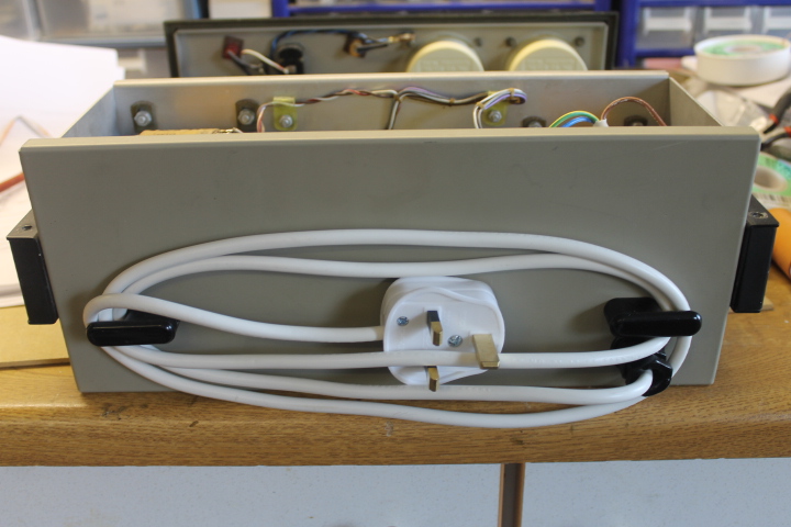
- Remove the US mains lead and plug and replace with a European colour-coded mains cable and a new UK plug (page 23)
- Rewire the two mains transformers for 230VAC operation (manual pages 19 to 22)
- Replace the mains slow blow fuse (1.5A for 115VAC operations with a 1A fuse for 230VAC operation (note on page 21))
- Replace any obviously over heated or damaged components (there were none)
- Check all of the resistors for their value against specification (pages 3 and 4)
- Replace all of the electrolytic capacitors with new parts (pages 3 and 6)
I was not going to immediately replace any of the valves but wait to see how they performed first. I have all of the smaller valves already and the main regulator valves are easy to obtain on Ebay. I might get a spare set at some stage.
My plan was to bring the power supply in to use in the workshop, not to restore it for display in a museum. The unit was in a very good clean condition and my experience with exploding or leaking electrolytic capacitors is not a happy one. But I have kept the original mains cable and electrolytics in case some one wants to undo all my changes…
Alterations
I have them here as a series of before and after photographs
Replacement mains cable
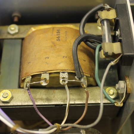
Rewire Mains Transformer T1
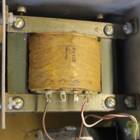
The two primary windings are now in series.
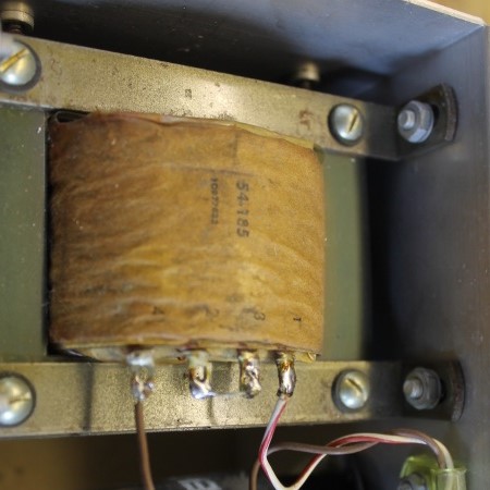
Rewire Mains Transformer T2
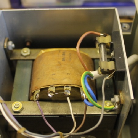
Again, the two primary windings are now in series. Note that the white/brown wire still connects to the centre contacts on T2 as it provides 115VAC to the two front panel neon bulbs. The new colour coded mains cable is visible.
Resistor Checking
I have read on the internet of other people's problems with resistor that have drifted high in value so I went through the unit with a multimeter checking the resistor values. In some cases there are alternative paths around resistors (especially R10 to R15) and I unsoldered one end to break any other resistive path. The only resistor I found out of specification was R20 which should have a value of 22k (10% tolerance) and I measured 218K. Now this was odd, the resistor looked orginal, and you could image the colour bandings were red-red-yellow rather than red-red-orange. So was 22k correct or should it be 220k and the schematic and manual are wrong? This resistor provides some overload protection for the bias voltage output and in series with a 150k resistor to the COMMON rail. When I tested the unit, the maximum bias voltage was about -70V DC as expected from this potential divider. So during testing phase (described below) I fitted a replacement 22k 0.5W 5% resistor and the maximum bias voltage rose to about -125V DC. I just wonder if the unit was built with a 220k resistor and the bias output has never been needed above -70V? I think I'll never know.
Electrolytic Capacitor Replacement
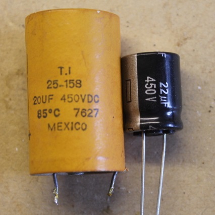
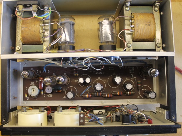
I decided to replace all of the electolytic capacitors as they are nearly 40 years old. The mess they can make if they leak or explode was worth avoiding for the loss of originality IMHO. The replacements were all Panasonic and as near a value match as I could achieve: 68uF for 70uF, 47uF for 40uF, 22uF for 20uF and I fitted 350V or 450V parts as specified. The only other difference was I used 105°C capacitors and the specifiction was 80°C. The replacements were all much smaller, for example:
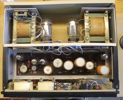
The replacement capacitors are clearly seen in the "before" and "after" top views of the unit:
Testing
The manual has a section on "Testing and adjustment" (pages 25 & 26) and a section entitled "In case of difficulty" (page 30). I basically followed the testing and adjustment procedure for a newly built unit. I was not (too) concerned about wiring errors as this was a built and had been a working unit. During this process the suspect resistor in the bias supply output was changed.
Happy Conclusion
Yippeeeee… I have a fully working Heathkit IP-17 power supply!
